
Back support device

a back support and back support technology, applied in the field of back support devices, can solve the problems of inability to provide support that is suitable for users of different physical dimensions and postures, lack of effective support and heat application, and impaired individual element effectiveness

Inactive Publication Date: 2005-02-24
SCHENCK DAVID
View PDF9 Cites 53 Cited by
  • Summary
  • Abstract
  • Description
  • Claims
  • Application Information

AI Technical Summary

Benefits of technology

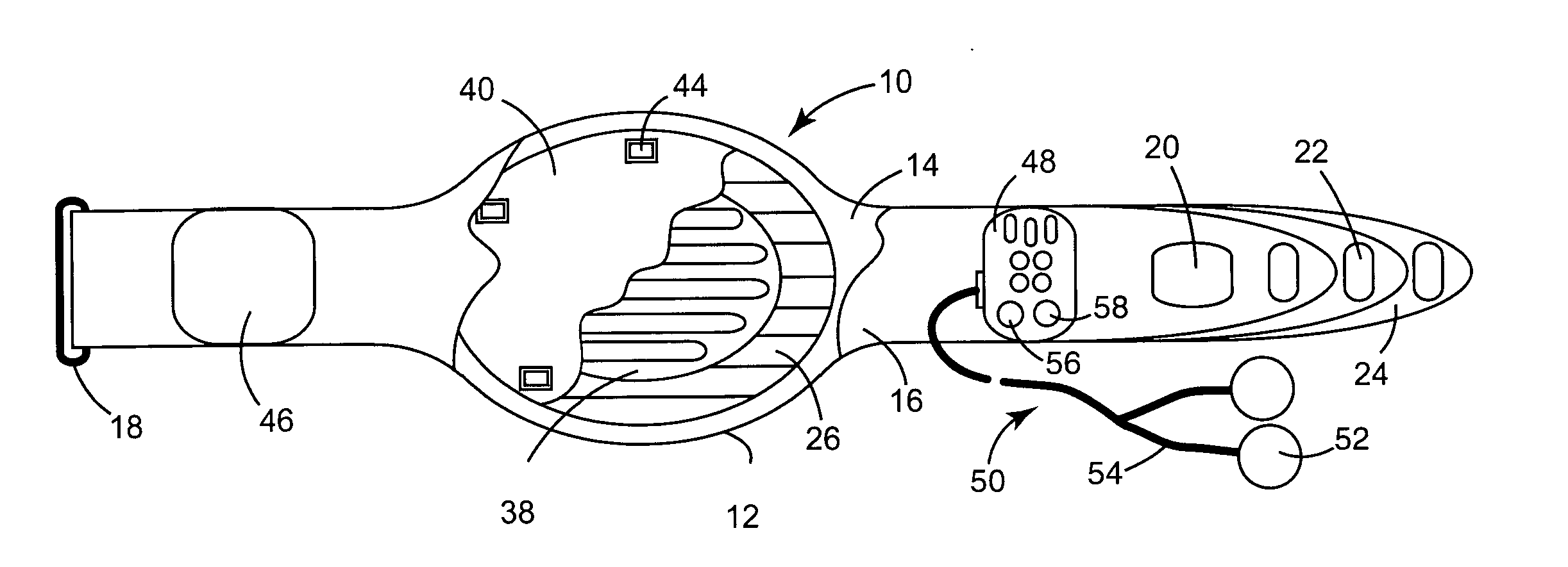
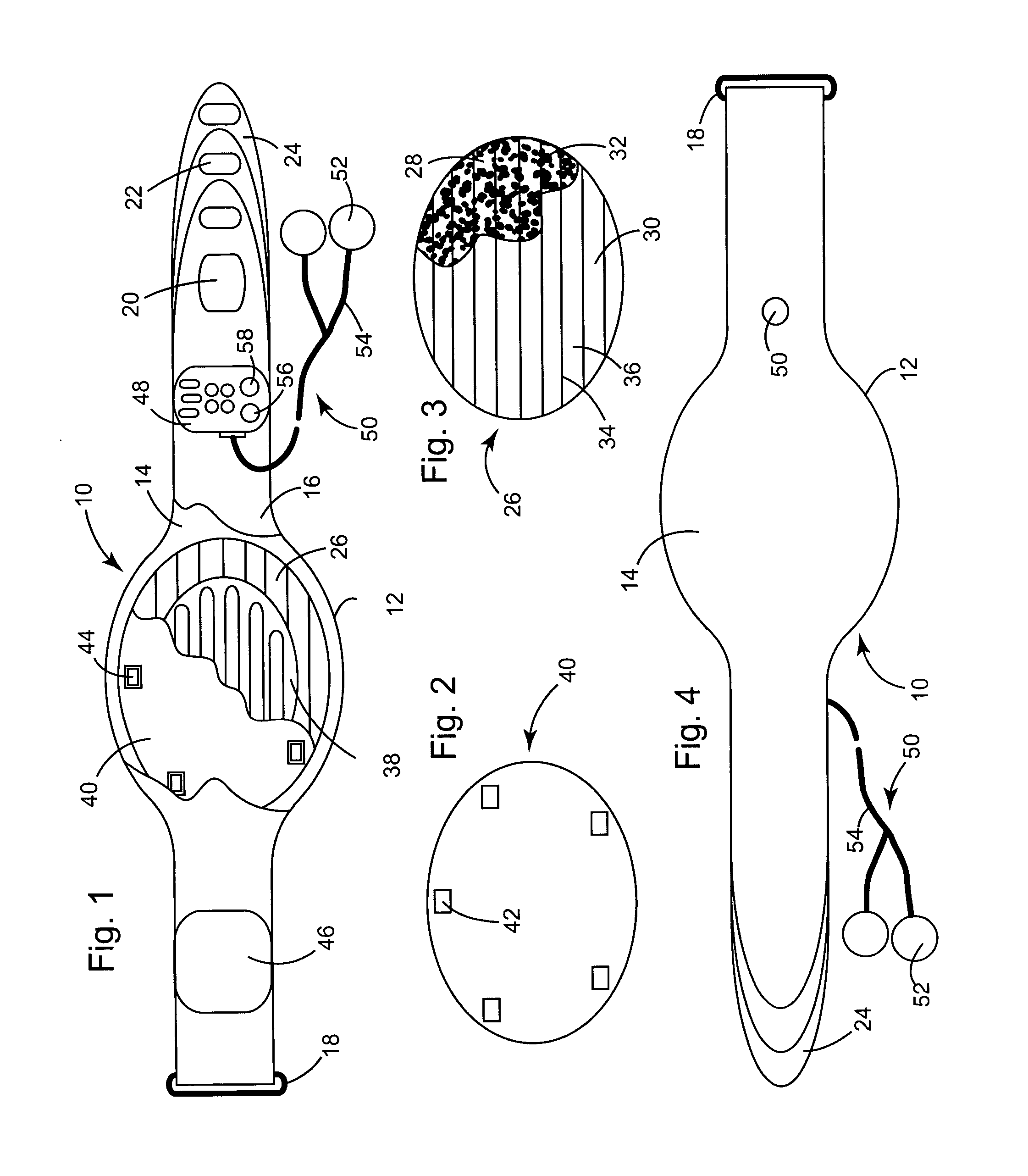
[0019] The vibrators may be positioned on the inside or even the outside surface of the back support plate. Preferably, however, the back support plate includes a plurality of vibrator receiving openings spaced outside of the periphery of the heating element, but inside the periphery of the back support plate and the heat transfer pad, with the vibrators being mounted within the back support plate openings. In this manner, the vibrators are in direct contact with the heat transfer pad, providing the greatest transfer of the vibrations and resulting massaging action to the user.

Problems solved by technology

While numerous prior art back support designs are known, a support that is suitable for users of differing physical dimensions and postures is not available.
As a result, merely positioning a support plate and / or heating element adjacent the user's back will result in areas of high and low pressure, causing discomfort and a lack of effective support and heat application.
However, when an attempt is made to combine a back support with a heat source and a vibration means in a lumbar belt, the effectiveness of the individual elements is impaired by the presence of the other elements.

Method used


Image

  • Back support device
  • Back support device

Examples


Embodiment Construction

[0028] In the following description, terms such as horizontal, upright, vertical, above, below, beneath, and the like, are used solely for the purpose of clarity in illustrating the invention, and should not be taken as words of limitation. The drawings are for the purpose of illustrating the invention and are not intended to be to scale.

[0029] As best illustrated in FIG. 1, the back support device, generally 10, is comprised of a belt 10 having an inner covering 12 and an outer covering 16 that are joined along their outer edges to form an interior cavity for receiving other components. The outer ends of belt 10 are releasibly attached with a loop 18 and mating hook-and-loop fasteners 20 and 22 joinable around loop 18. One of the outer ends of belt 10 includes scored tips 24 that can be detached, e.g., by cutting, to shorten belt 10 to accommodate a user with a smaller waist.

[0030] Heat transfer pad 26, also illustrated in FIG. 4, is positioned adjacent inner cover 14. Pad 26 is ...


PUM


Abstract

A back support device for heating and stimulating the nerves of a user's back includes a belt having inner and outer coverings, a conformable heat transfer pad having inner and outer coverings joined to each other to form discrete sections that are filled with a particulate heat retention material, a heating element adjacent the outer side of the heat transfer pad, a back support plate adjacent the outer side of the heating element, and at least one nerve stimulator. The nerve stimulator may be formed of a plurality of vibrators, a transcutaneous nerve stimulator, or both. A battery and a controller power and control the heating element and the nerve stimulator. The heat transfer pad and back support plate are preferably of approximately the same shape and size, while the heating element is of a smaller size, permitting the vibrators to contact the heat transfer pad.

Description

BACKGROUND OF THE INVENTION [0001] (1) Field of the Invention [0002] The present invention relates to a back support device that is used to support a user's back while simultaneously providing relief from backache through the application of a combination of heat and nerve stimulation. [0003] (2) Description of the Prior Art [0004] Back supports and belts that provide heat to a user's back are known in the prior art as exemplified by U.S. Pat. No. 4,702,235 to Hong; U.S. Pat. No. 5,062,414 to Grim; U.S. Pat. No. 5,928,275 to Yates et al.; U.S. Pat. No. 5,891,189 to Payne, Jr.; and U.S. Pat. No. 5,378,225 to Chatman, Jr. et al. This latter patent also discloses that elements can be incorporated into the belt to generate vibrations to massage the user's back. [0005] While numerous prior art back support designs are known, a support that is suitable for users of differing physical dimensions and postures is not available. Back supports are normally comprised of a belt or strap that is a...

Claims


Application Information

Patent Timeline
IPC IPC(8): A61H11/00A61H23/02A61N1/24A61N1/34
CPCA61H11/00A61H23/02A61H2205/081A61N1/0456A61N1/36021A61N1/321A61N1/24
Inventor SCHENCK, DAVID
Owner SCHENCK DAVID
Learn More