Self-donning surgical gown

Inactive Publication Date: 2005-03-03
KIMBERLY-CLARK WORLDWIDE INC
View PDF36 Cites 53 Cited by
  • Summary
  • Abstract
  • Description
  • Claims
  • Application Information

AI Technical Summary

Problems solved by technology

Furthermore, these gowns were costly and required laundering and sterilization procedures prior to reuse.
However, there are many surgical procedures that permit the use of surgical gowns that are not totally liquid impervious.
This is because traditional closure means used in disposable surgical gown

Method used


Image

  • Self-donning surgical gown
  • Self-donning surgical gown
  • Self-donning surgical gown

Examples


Embodiment Construction

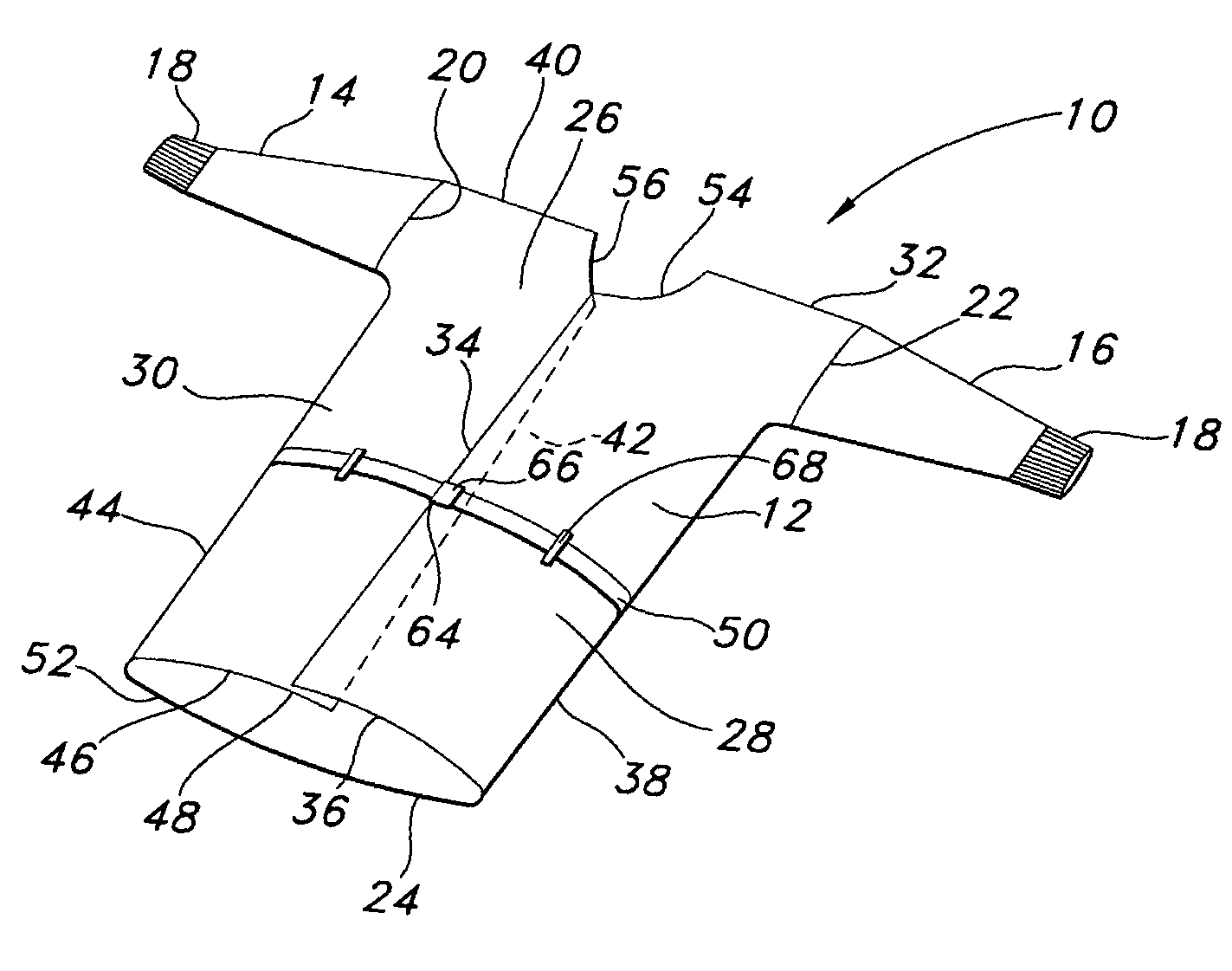
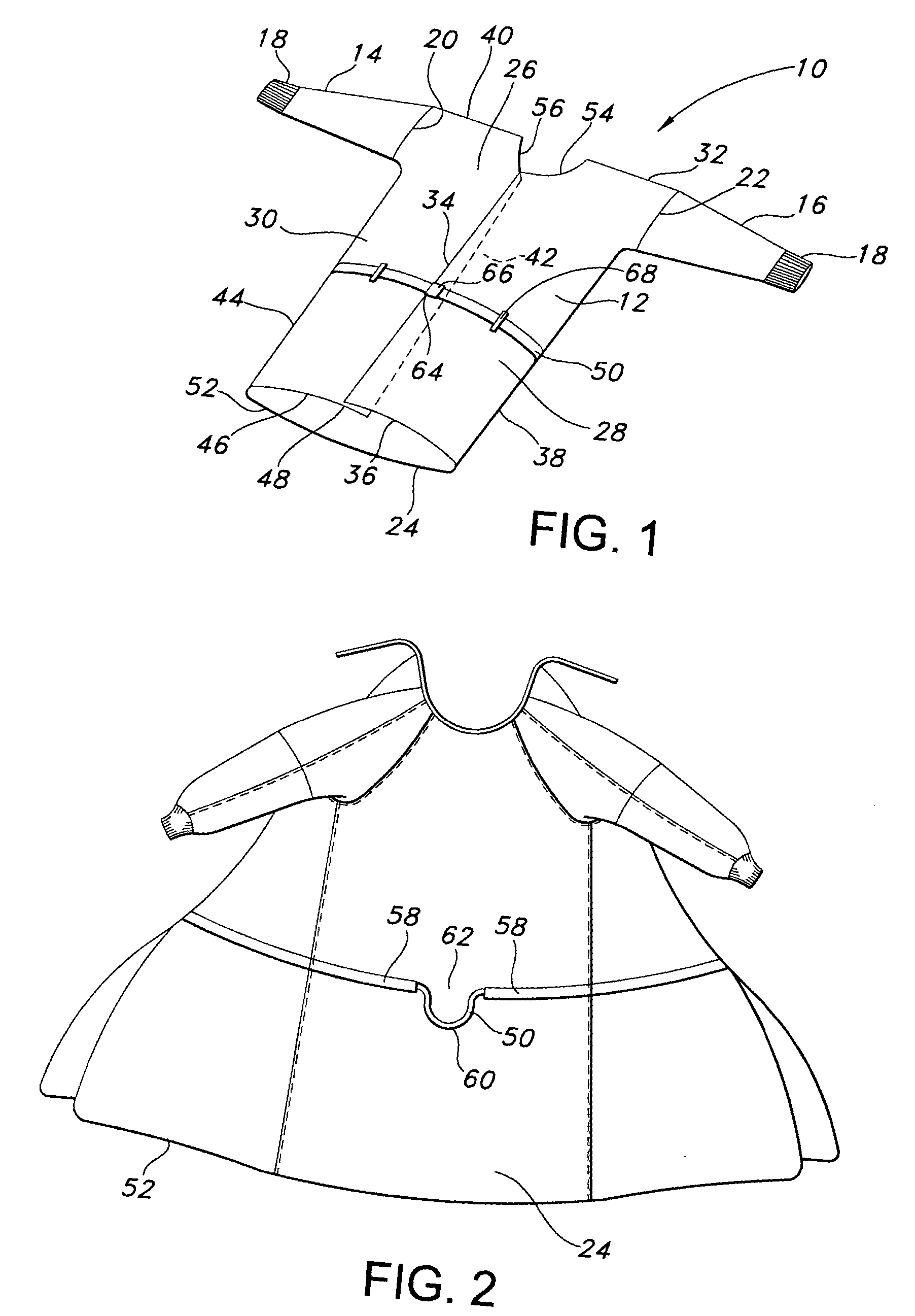
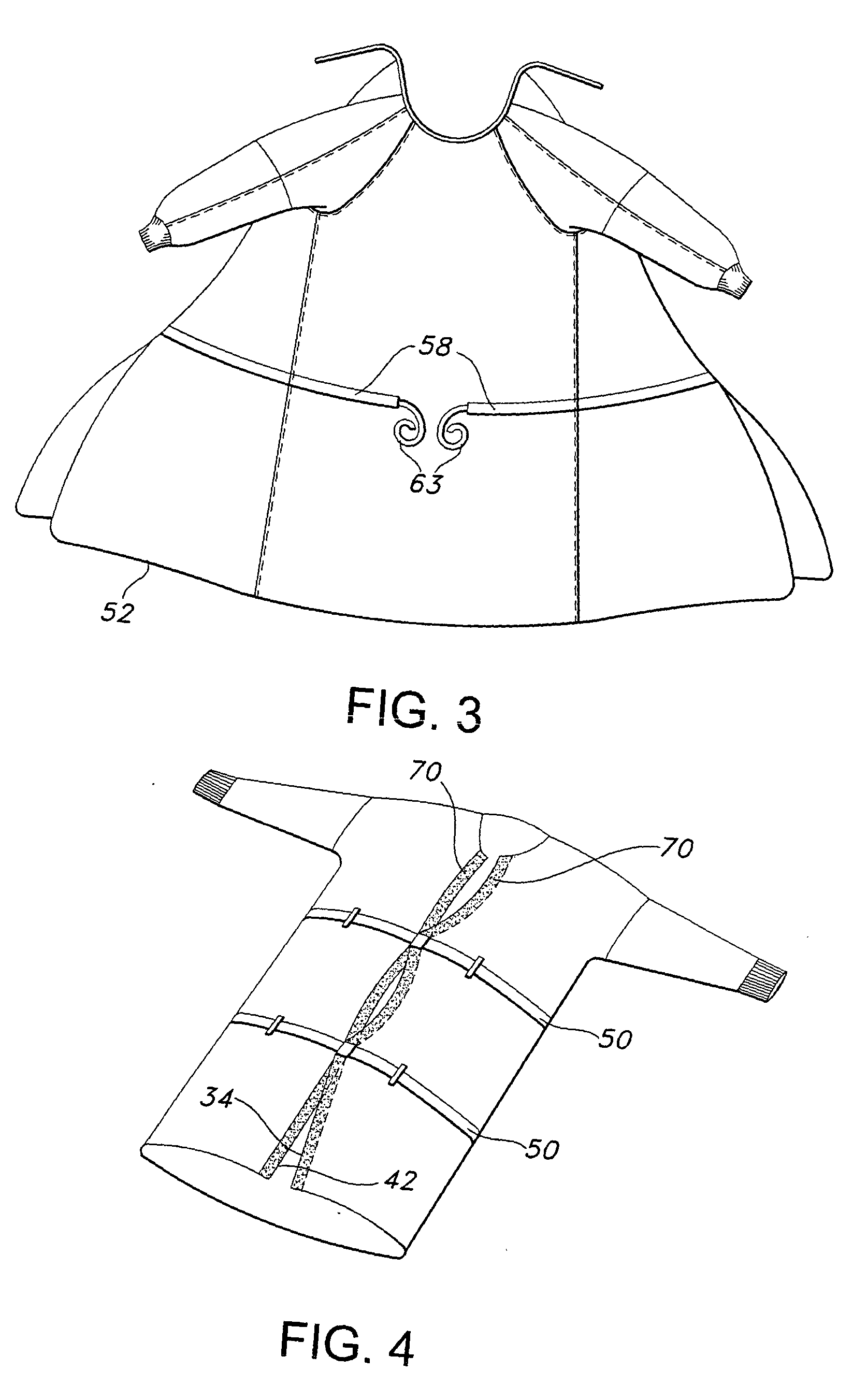
[0015] The present invention and its advantages are best understood by referring to the drawings, like numerals being used for like and corresponding parts of the various drawings.

[0016] Several terms may be used herein to refer to various parts of the gown as the gown is worn. Thus, “front” refers to that part of the gown which overlays the chest or anterior plane of the wearer; “back” refers to that part of the gown which overlays the back or posterior plane of the wearer, “side” or “sides” refer to that part of the gown which overlays the side or lateral portion(s) of the wearer and which may extend to and overlap the back or front portions of the wearer and are generally located between the front and the back. The term “outer” or “outside” describes that surface of the gown which faces away from the wearer when the gown is being worn; “inner” or “inside” refers to the surface of the gown, or part thereof which faces either the clothes or body of the wearer, while “right” and “l...


PUM


Abstract

The invention relates to a nonwoven gown made of a gown body terminating in two edges at a back of the gown. The gown contains a closure member that extends around the gown body and terminates at each edge. Manipulation of the closure member moves at least one of the edges toward the other thereby closing the back of the gown. A fastener located along at least a portion of at least one of the edges may be provided. Some suitable fasteners include tape, hook and loop type fasteners, and/or snaps. Such a gown enables a wearer to close and secure the gown by himself while keeping his hands sterile.

Description

BACKGROUND [0001] The present invention relates to gowns and other garments and particularly to surgical gowns. More particularly, this invention relates to improved gown closure mechanisms that enable a gown wearer to close the back of a gown without moving his hands outside a region commonly referred to as the “sterile zone” thus minimizing the risk of hand contamination prior to a surgical procedure. [0002] As is generally known, sterile surgical gowns are designed to greatly reduce, if not prevent, the transmission through the gown of liquids and biological contaminants that may become entrained therein. In surgical procedure environments, such liquid sources include the gown wearer's perspiration, and patient liquids including blood and life support liquids such as plasma and saline. [0003] Surgical gowns were originally made of cotton or linen and were sterilized prior to use in the operating room. These gowns, however, permitted transmission or “strike-through” of various liq...

Claims


Application Information

Patent Timeline
IPC IPC(8): A41D13/12A41F17/00
CPCA41D13/1209A41D2400/44A41F1/00
Inventor AMBROSE, JULIAKATHUMBI-JACKSON, DEANNA
Owner KIMBERLY-CLARK WORLDWIDE INC
Why Eureka
Try Eureka