Retractable cover with biasing mechanism for covering structures

a technology of a sliding mechanism and a retractable cover, which is applied in the direction of curtain accessories, curtain suspension devices, building components, etc., can solve the problems of securing or storing the window or door cover, the process of manipulating the same cover for either or both use and storage, and the person getting cold or wet, so as to achieve convenient storage and protect from the elements

Inactive Publication Date: 2005-03-03
ULLYETT GORDON JEFFREY
View PDF26 Cites 19 Cited by
  • Summary
  • Abstract
  • Description
  • Claims
  • Application Information

AI Technical Summary

Benefits of technology

[0037] It is also an object of the present invention to provide a system which allows for a substantially trouble free installation.
[0081] Use of the retractable cover in the trucking industry allows for quick retraction of covers, speeding access to goods and ensuring the cover is kept out of the way of loading and unloading. Use of the same cover in outside cafes and stalls and the like to create shelter against the elements allows for quick packing up of a site at closing, and easy storage of the covers when not in use. The ability to attach the same cover to a cafe or stall by a detachable means such as a hook-and-pile fastener also has the advantage of allowing the covers to be brought inside overnight and therefore protected from the elements, theft or vandalism.

Problems solved by technology

In all cases where a cover is required, the means of storing the cover when not in use, the application of that cover when required, and the process of manipulating the same cover for either or both use and storage, can be both tedious and time consuming.
When a person is camping in a tent or residing in a caravan awning, securing or storing the window or door covers is a tedious process.
In poor weather situations, the time taken to put a cover in place can lead to the person getting cold or wet.
In a freight-trucking situation, folding back a cover to expose goods for transfer can take time and restrict access to goods while unloading.
Such systems may be bulky, include a number of parts which may become damaged, or worn and require replacement, and do not allow for different extensions of one elongate side edge of the material compared to the other such that the cover may lie partially unwound in a substantially diagonal arrangement across the opening or structure, to enable the opening or structure to be only partially covered, if required.
Further, for some of these systems, the holder is a cumbersome object which is required to be fitted to the structure, requires storage when not in use and is not compact.
Further, the damage to the helical spring or winding mechanisms, or weakening thereof, may result in no, or imperfect, retraction of the cover into the holder.
Such material however would not be suitable as covers for tent doorways or windows, or for vehicle trailers, or as awnings where there is a need for greater flexibility of material, a need to roll up the covers to be substantially compact, and so forth.
Further, the potential coiling tension of the polyester sheet as a whole may limit the use of this material in situations where it would be useful to extend only one elongate side edge of the material in a manner which creates a substantially diagonal arrangement across the opening or structure, to enable the opening or structure to be only partially covered, if required, such as is often the case for a tent doorway, tent window covers, or the sides of awnings.
More specifically, it was with the problems associated with the lack of a readily available alternative system for achieving a cover capable of being quickly extended or retracted without the need for cumbersome systems such as rollers, or holders; therefore, a cover which may be made of a range of flexible materials as applied to tents, awnings, boat covers, trailer or truck deck covers, and so forth.

Method used


Image

  • Retractable cover with biasing mechanism for covering structures
  • Retractable cover with biasing mechanism for covering structures
  • Retractable cover with biasing mechanism for covering structures

Examples


Embodiment Construction

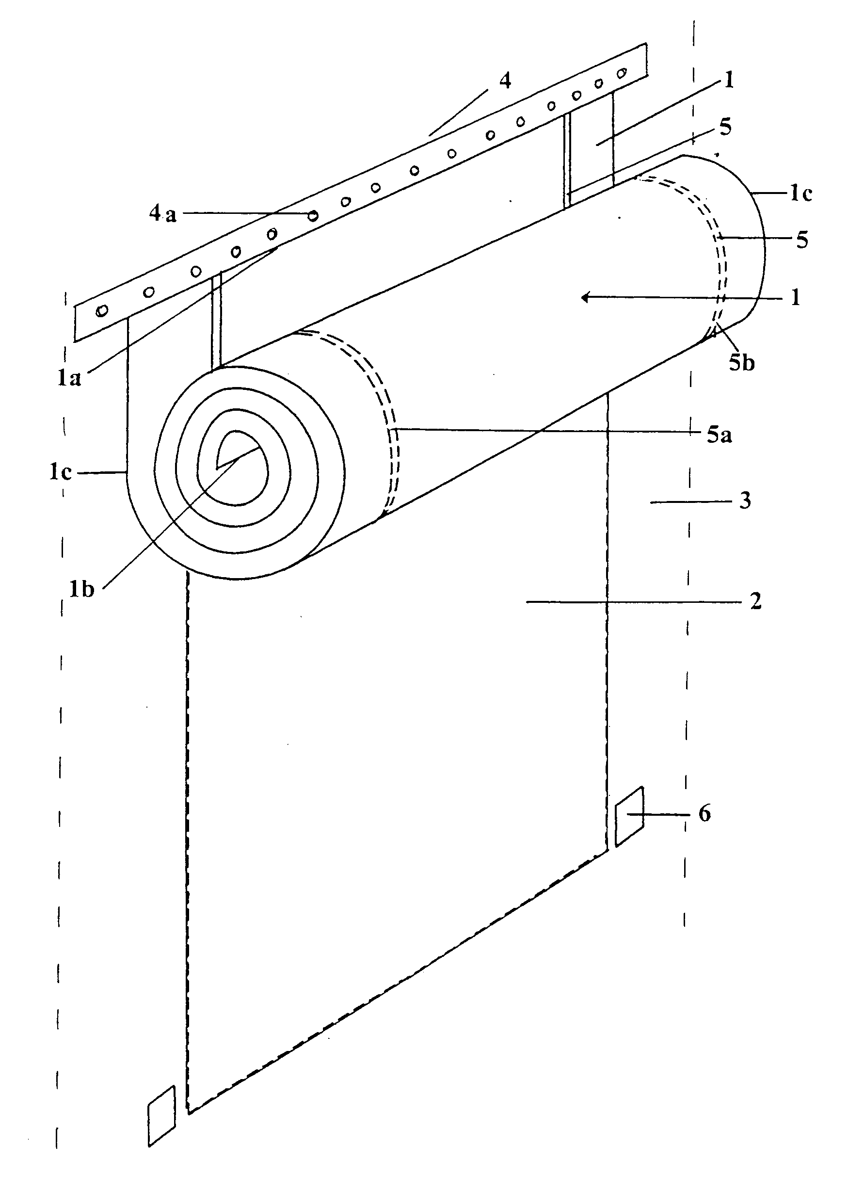
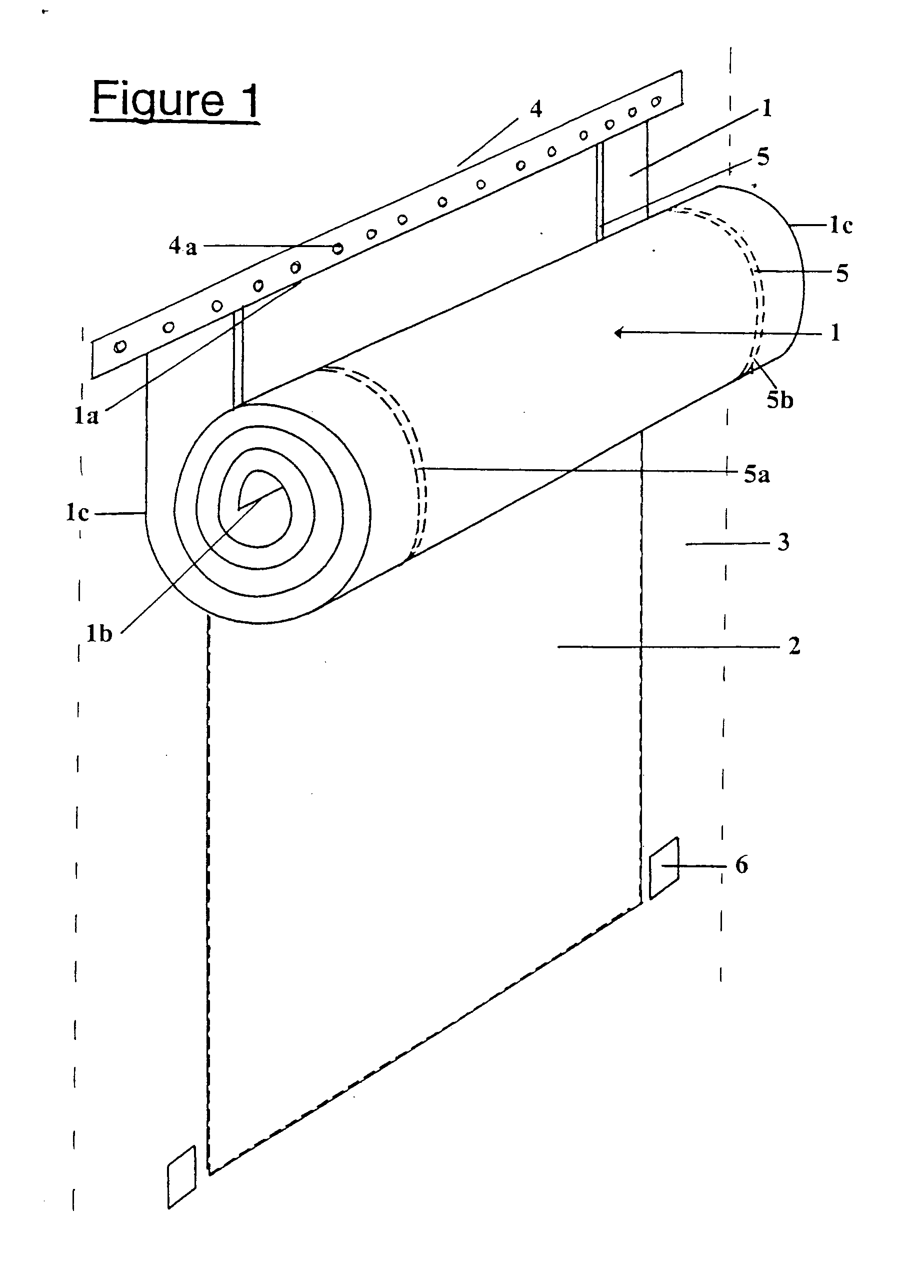
[0089] With reference to the diagrams by way of example only, there is provided a retractable cover 1 with biasing means 5 for covering structures 3.

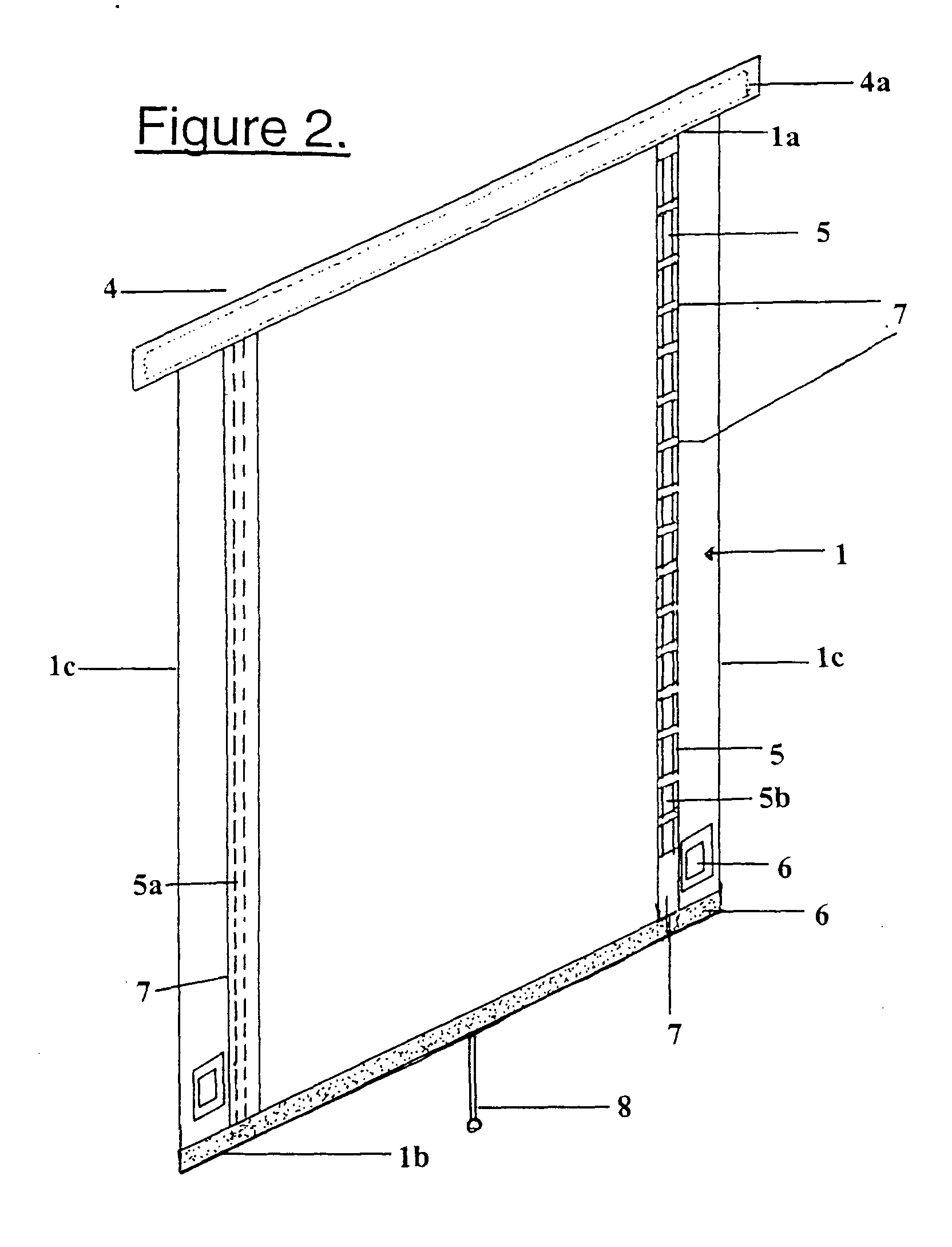
[0090] The cover 1 as illustrated in FIG. 1 is made from substantially flexible materials, such as fabric, canvas, plastic materials, rubber, and so forth. The cover 1 includes a top edge 1a, a bottom edge 1b, and two side edges 1c. The cover 1 is substantially rectangular in shape. However, the shape of the cover 1 is variable between embodiments and is dictated by the structure's size and shape with which the cover is used.

[0091] The cover 1 may be secured in relation to the structure, at any one or more of the edges of the cover, depending on the function the cover is designed to fulfill. The structure it is covering, in the illustrated example, is an opening 2, such as a window or doorway of a tent 3, for example. The cover is therefore secured to the surround adjacent the structure. In the illustrated examples, the cover is secur...


PUM


Abstract

A retractable cover which includes a flexible material portion having at least one biasing mechanism. The biasing mechanism is a spring with either constant or varied force that allows the flexible material to be rolled up. The retractable cover is particularly applicable to tents or temporary structures, but could also be applied to window covers, awnings, truck sidings boat canopies or the like. The biasing mechanism may be placed in a sheath which includes a zipper or the like, so that the biasing mechanism can be easily replaced or added to. Additionally, zippers can be positioned at the sides of the retractable cover to allow the securing of the cover at any height.

Description

BACKGROUND OF THE INVENTION [0001] 1. Field of the Invention [0002] This invention relates to a retractable cover with biasing mechanism for covering structures. [0003] In particular, it relates to a retractable cover that includes a flexible material portion and at least one biasing means enabling the cover to automatically retract from an extended state and thus allows the flexible material to be rolled up. The retractable cover is particularly applicable to tents or temporary structures, but could also be applied to window covers, awnings, truck sidings, trailer covers, boat canopies, or the like. However, the present invention may also have other applications outside this field. [0004] 2. Description of the Related Art [0005] The general method of covering an opening, enclosure or outdoor area is generally by a window, door, or a covering of some description. [0006] The term “door” or “window” usually refers to a solid structure in a house or the like which can be transparent, t...

Claims


Application Information

Patent Timeline
Patent Type & Authority Applications(United States)
IPC IPC(8): E04H15/32E06B9/24E06B9/78E06B9/80
CPCE04H15/32E06B9/80E06B9/78E06B9/24
Inventor ULLYETT, GORDON JEFFREY
Owner ULLYETT GORDON JEFFREY
Why Eureka
Try Eureka