

Dispenser
a technology for dispensers and rotatable caps, applied in the field of dispensers, can solve the problems of compromising seals, rotatable caps are also less desirable to consumers, and rotatable caps may also be less desirable functionally
- Summary
- Abstract
- Description
- Claims
- Application Information
AI Technical Summary
Benefits of technology
Problems solved by technology
Method used
Image

Examples
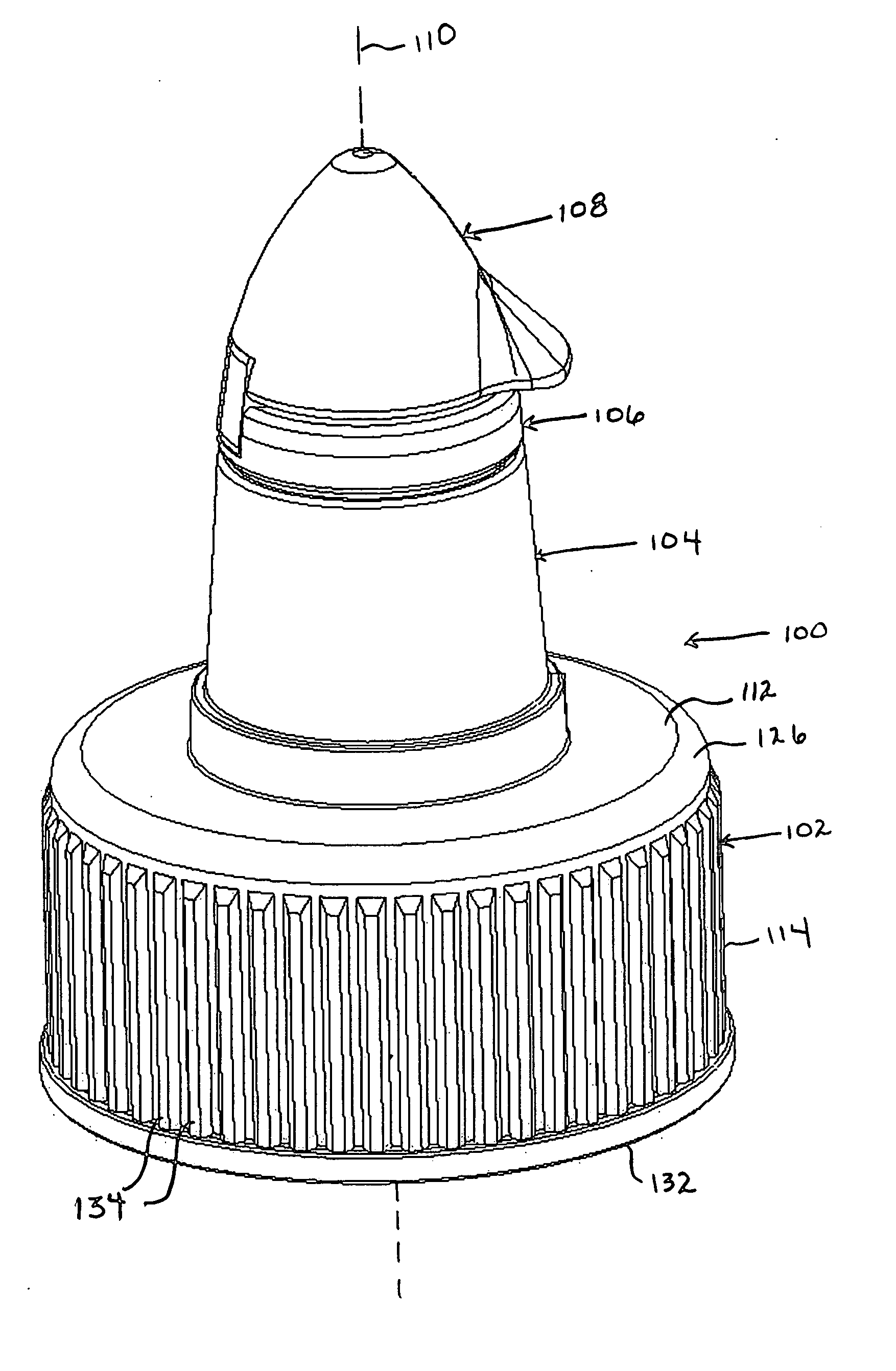
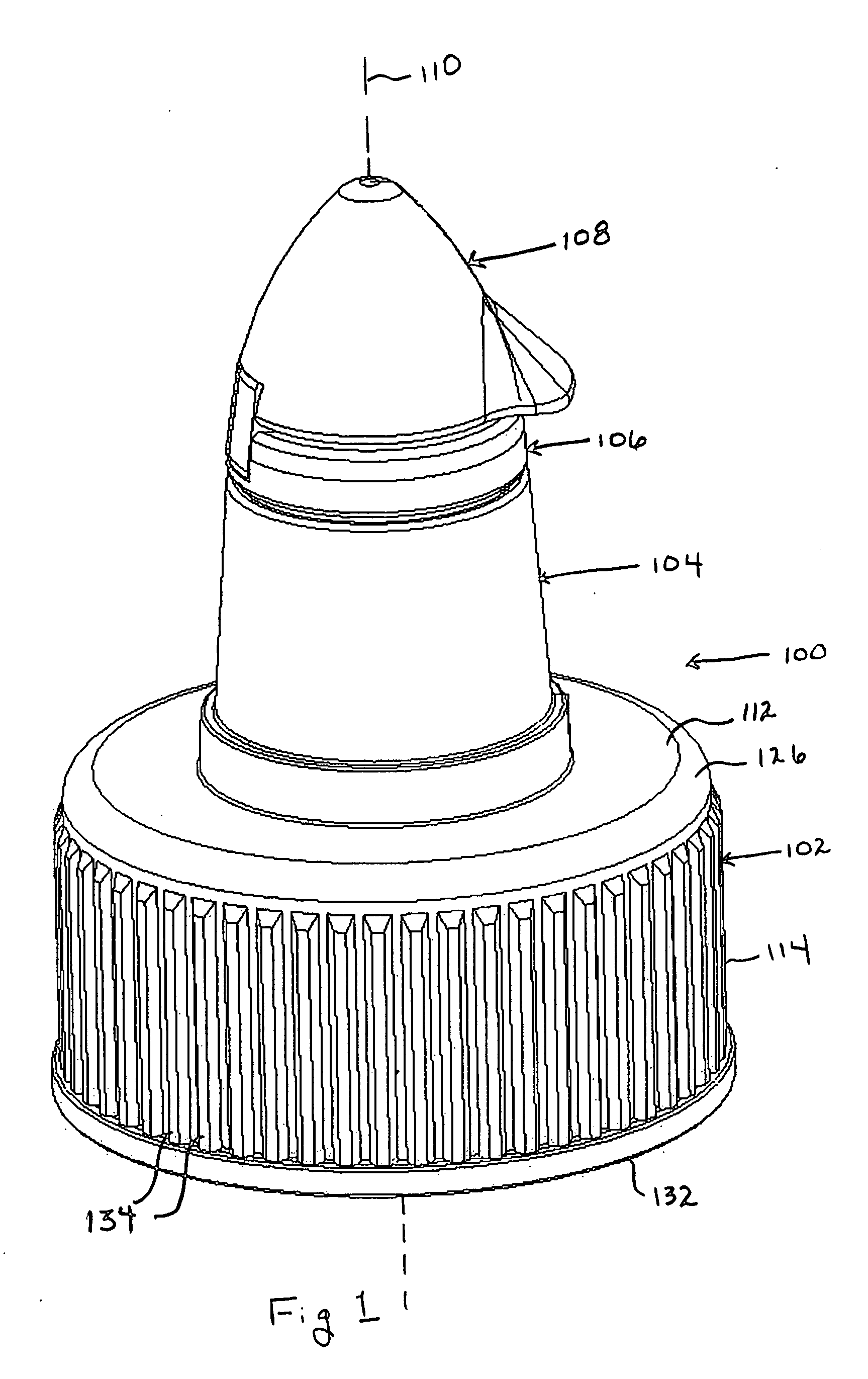
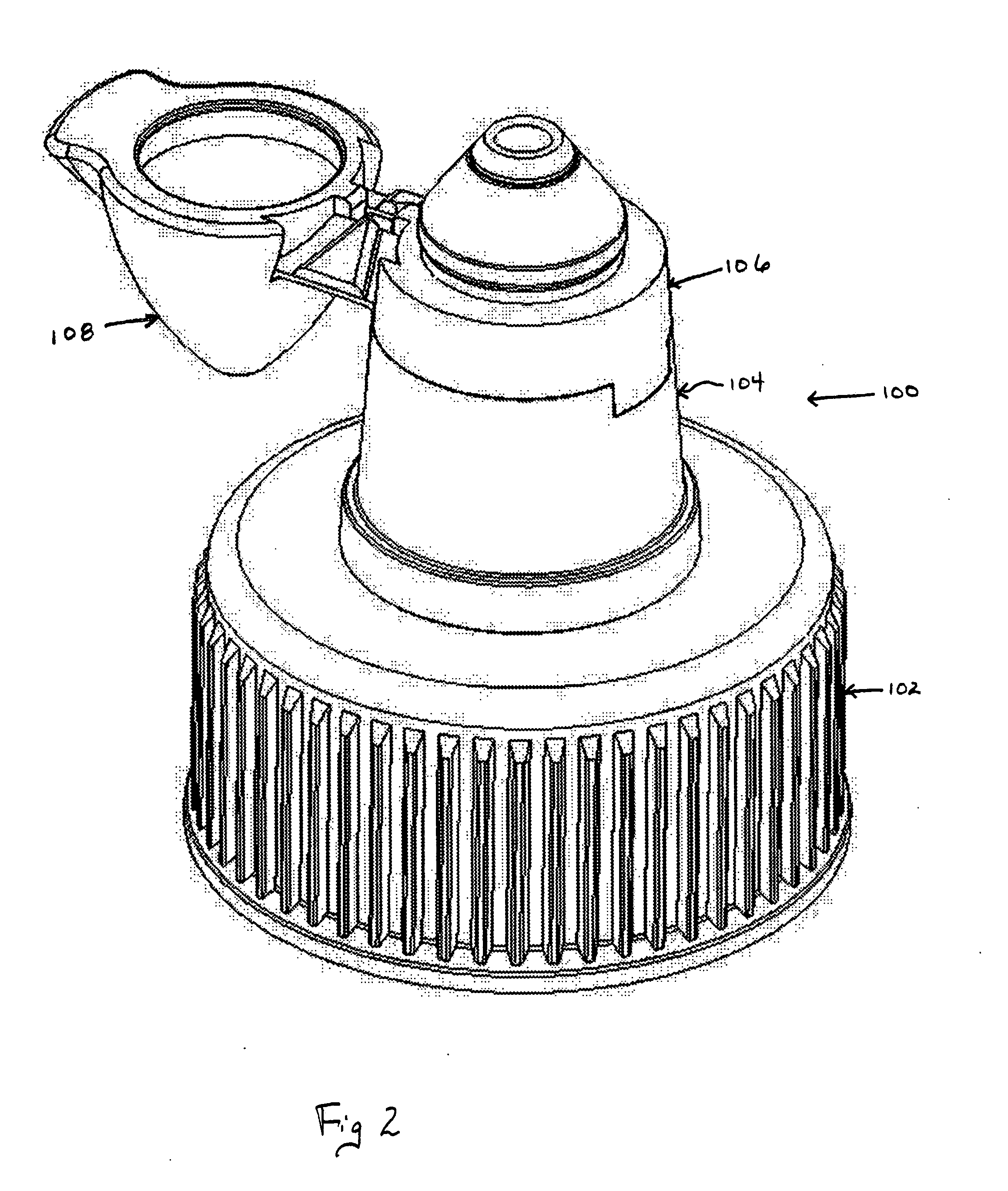
first embodiment
[0054] Suitable materials for the present dispenser include polyethylene, e.g., high density polyethylene, and polypropylene. However, other suitable materials can be found in the Handbook of Plastics, Elastomers, and Composites, Third Edition, Charles A. Harper, Editor-in-Chief, McGraw-Hill, New York (1996), the entire disclosure of which is hereby incorporated by reference. Individual components of the present dispenser may be formed by processes such as injection molding utilizing the foregoing materials.
[0055] The first embodiment of present dispenser is assembled by extending the first member 104 through the base collar opening 122 until the flange upper surface 156 contacts the base collar lower surface 120 and the tabs 124 are accommodated in the flange slots 154. The second member 106 is forced into position, wherein the upper extension 152 is accommodated within the bore 222 and the second member tabs 210 are accommodated in the first member slots 180. The cap 108 is closed...
second embodiment
[0066] Suitable materials for the present dispenser include polyethylene, e.g., high density polyethylene, and polypropylene. In one situation, the collar 302 is made from high density polyethylene and the cap 308 and cone 304 are made from polypropylene. However, other suitable materials can be found in the Handbook of Plastics, Elastomers, and Composites, Third Edition, Charles A. Harper, Editor-in-Chief, McGraw-Hill, New York (1996), previously incorporated by reference. Individual components of the present dispenser may be formed by processes such as injection molding utilizing the foregoing materials.
[0067] As best seen in FIGS. 20 and 21, the second embodiment of present dispenser is assembled by extending the first member 304 through the base collar opening 322 until the flange upper surface 356 contacts the base collar lower surface 320 and until the collar upper member 312 is disposed in the slot 362. The second member 306 is forced into position, wherein the upper extensio...
PUM
 Abstract
Description
Claims
Application Information