Method and apparatus for making a blow molded fuel tank

a fuel tank and blow molding technology, applied in the field can solve the problems of increasing the scrap rate of blow molding fuel tanks, and achieve the effect of reducing or illuminating downstream processing operations and removing flash

Active Publication Date: 2005-03-03
TI GRP AUTOMOTIVE SYST LLC
View PDF8 Cites 11 Cited by
  • Summary
  • Abstract
  • Description
  • Claims
  • Application Information

AI Technical Summary

Benefits of technology

[0004] A fuel tank is formed by a blow molding apparatus and method wherein a blow pin is communicated with an interior of a parison received in a blow mold so the parison may be blown to shape within the mold cavity by introduction of a pressurized gas from the blow pin into the interior of the parison. When the blow pin is no longer needed, it is retracted from the mold and a pinch plate assembly is used to close off the opening in the molded part created by the blow pin. The pinch plate assembly may also remove flash to reduce or illuminate downstream processing operations. Thereafter, the mold may be opened and the molded part removed, the pinch plate assembly moved back to its retracted position, and the blow pin may be advanced into the open mold for use with a subsequent parison so that a subsequent parison can be blow molded in the same manner.

Problems solved by technology

Also, there is a potential for failure in attaching the cover or plug to the fuel tank resulting in an increased scrap rate of fuel tanks produced by a blow molding operation.

Method used


Image

  • Method and apparatus for making a blow molded fuel tank
  • Method and apparatus for making a blow molded fuel tank
  • Method and apparatus for making a blow molded fuel tank

Examples


Embodiment Construction

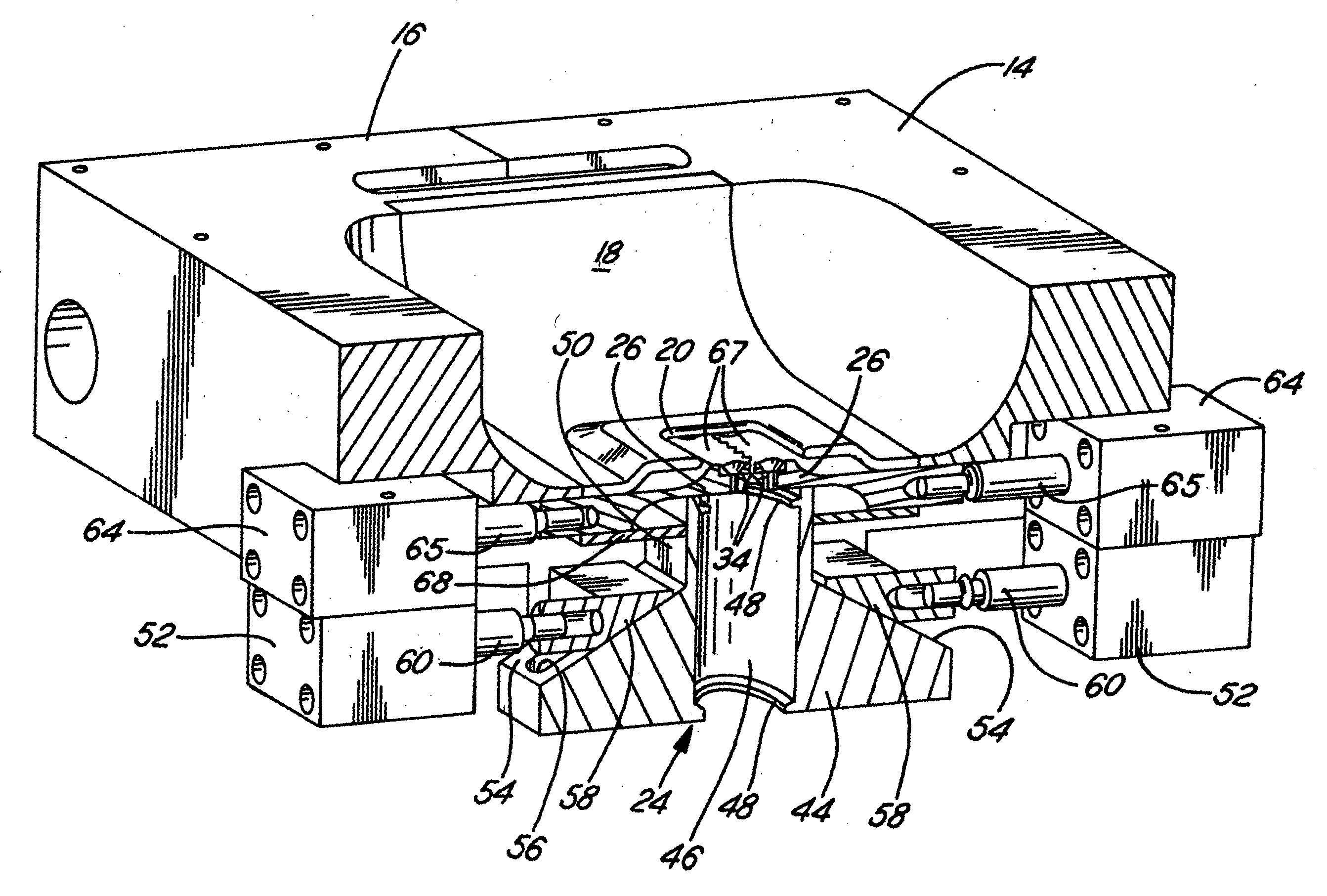
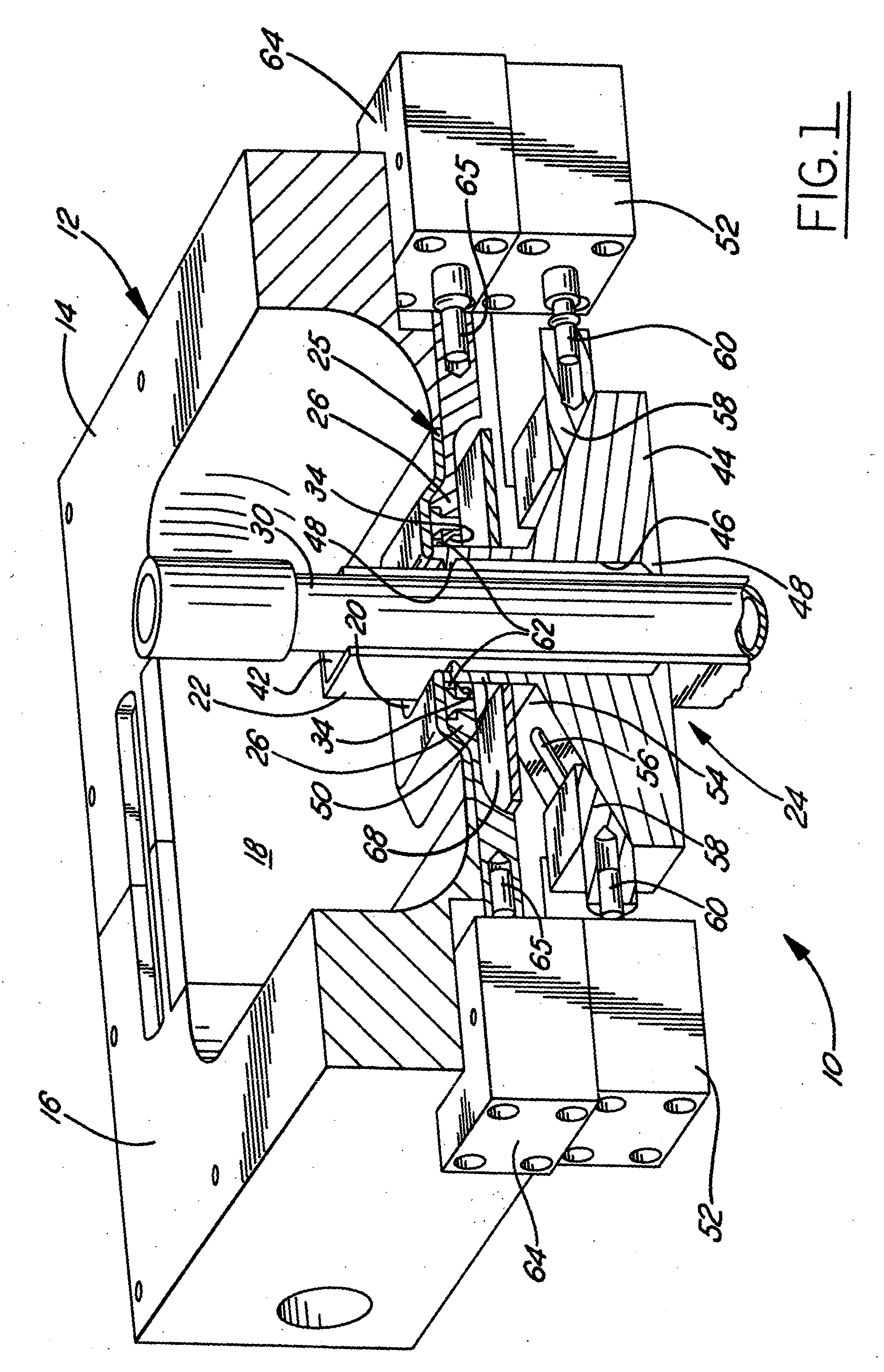
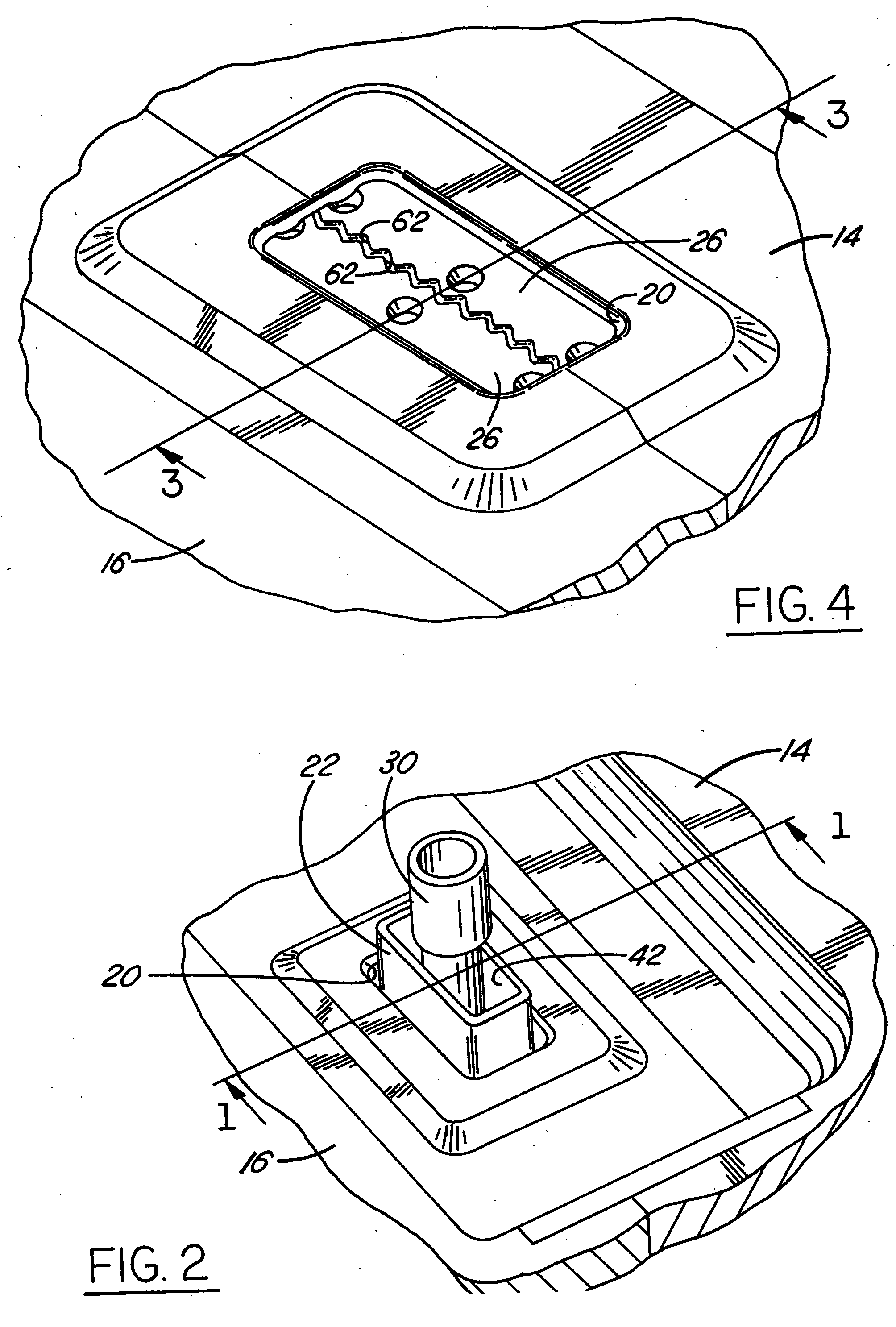
[0012] Referring in more detail to the drawings, FIG. 1 illustrates a blow molding apparatus 10 according to one presently preferred embodiment of the invention. The blow molding apparatus 10 includes a mold 12 having a pair of mold halves 14, 16 (only partially shown in FIGS. 1 and 3) which may be moved between open and closed positions to receive a parison and to enable the parison to be blow molded, respectively. The mold halves 14, 16 define a mold cavity 18 in which the parison is received and formed into its final shape. An opening 20 in the mold 12 receives a blow pin 22 of a blow pin assembly 24 that provides pressurized gas, such as air, into an interior of a parison to expand it outwardly into the mold cavity 18. A pinch plate assembly 25 includes a pair of pinch plates 26 moveable between an open position (shown in FIG. 1) wherein the pinch plates 26 are spaced from each other and a closed position (FIGS. 3 and 4) wherein the pinch plates preferably engage and pinch close...


PUM

PropertyMeasurementUnit
temperatureaaaaaaaaaa
areaaaaaaaaaaa
forceaaaaaaaaaa

Abstract

A fuel tank is formed by a blow molding apparatus and method wherein a blow pin provides pressurized gas into an interior of a parison received in a blow mold so the parison may be blown to shape within the mold cavity. When the blow pin is no longer needed, it is retracted from the mold and a pinch plate assembly is used to close off the opening in the molded part created by the blow pin. Thereafter, the mold may be opened and the molded part removed, the pinch plate assembly and moved back to its retracted position, and the blow mold pin may be advanced into the open mold for use with a subsequent parison so that the subsequent parison can be blow molded in the same manner.

Description

FIELD OF THE INVENTION [0001] This invention relates to a method and apparatus for forming a fuel tank, and more particularly a blow molded fuel tank. BACKGROUND OF THE INVENTION [0002] Generally, in a blow molding process, a parison is extruded in a size and of an amount of material sufficient to create a desired part. The parison is placed into an open mold in which a blow pin may be oriented, and the mold is closed around the parison. Portions of the parison are pinched between halves of the mold as the mold is closed, and the parison is preferably received around the blow pin. A gas under pressure, such as air, is introduced into the interior of the parison through the blow pin to outwardly expand the parison into the mold and conform the parison to the shape of the mold cavity. [0003] After the blowing procedure, the blow pin may be retracted from the mold and the molded part removed from the mold. Flashing is removed from the molded port at a trimming station, and other second...

Claims


Application Information

Patent Timeline
Patent Type & Authority Applications(United States)
IPC IPC(8): B29C49/48B29C49/02B29C49/04B29C49/30B29C49/58B29C49/60B29L22/00
CPCB29C49/04B29L2031/7172B29C49/58B29C49/4802B29C49/42802B29C49/02B29C49/30
Inventor BRANDNER, BRIAN W.KERSEY, KEITH D.KNUEPPEL, HARALDQUICK, CHRISTOPHER K.
Owner TI GRP AUTOMOTIVE SYST LLC
Why Eureka
Try Eureka