A Friction Stir Welding Method Using Magnetic Force to Realize Back Support

A technology of friction stir and welding methods, applied in welding equipment, non-electric welding equipment, metal processing equipment, etc., can solve the problems of low viscosity, difficult to achieve plastic material wrapping, easy softening, etc., achieve flexible replacement, eliminate root defects, eliminate The effect of arc-shaped defects

Inactive Publication Date: 2021-03-12
HARBIN INST OF TECH
View PDF7 Cites 0 Cited by
  • Summary
  • Abstract
  • Description
  • Claims
  • Application Information

AI Technical Summary

Problems solved by technology

During the welding process, the welding tool is directly inserted into the workpiece to be welded, and the lower support acts as a support and prevents the material from overflowing, thereby eliminating root defects. However, due to the low viscosity of the polymer matrix composite material and its easy softening when heated, self-supporting welding tools are difficult Realize the wrapping of plastic materials

Method used


Image

  • A Friction Stir Welding Method Using Magnetic Force to Realize Back Support

Examples


Embodiment Construction

[0025] The technical solutions in the embodiments of the present invention will be clearly and completely described below in conjunction with the drawings in the embodiments of the present invention.

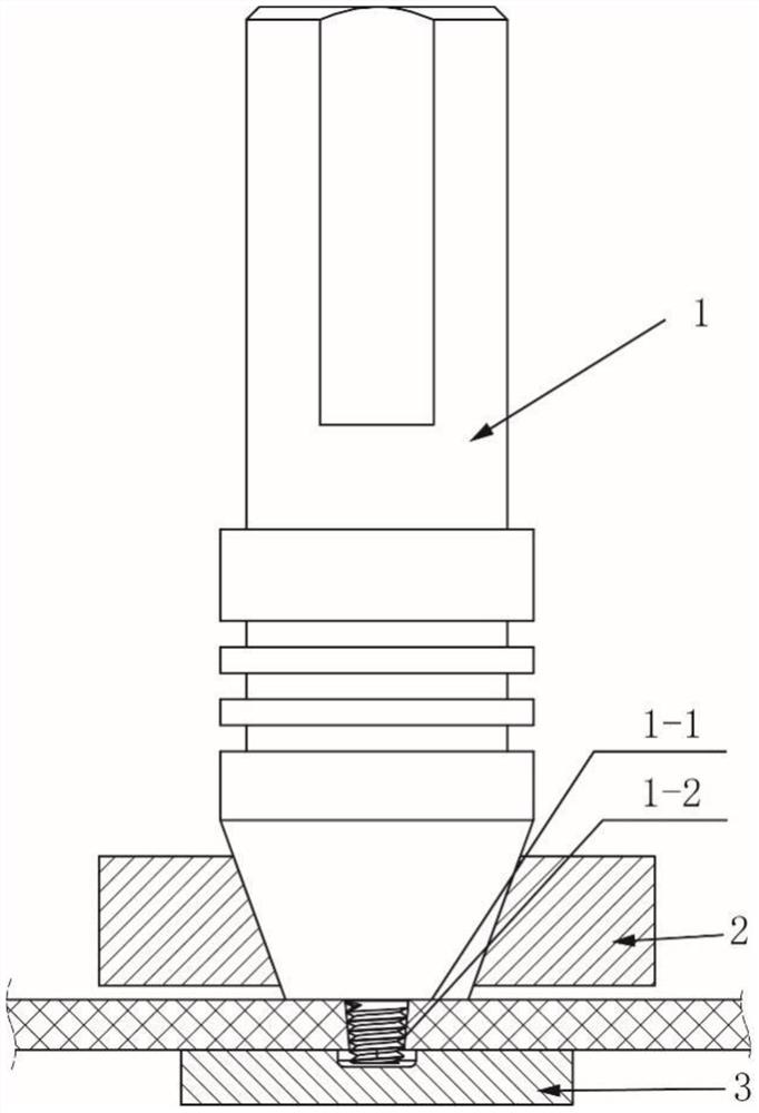
[0026] see figure 1 Describe this embodiment, a method of friction stir welding that realizes the back follow-up support through magnetic force, which includes the following steps:

[0027] Step 1: Clean up before welding, use an organic solvent or cleaning agent to wipe the plate to be welded to remove surface debris, and the plate to be welded is a thermoplastic polymer or thermoplastic polymer composite material plate;

[0028] Step 2: Use fixtures to clamp the plates to be welded so that the butt surfaces of the plates to be welded are close to each other;

[0029] Step 3: Nest the electromagnetic device 2 on the outside of the stirring head 1, the electromagnetic device 2 is connected to the welding machine and follows the stirring head 1 to perform synchronous plane movem...


PUM


Abstract

The invention provides a friction stir welding method for realizing back follow-up support through magnetic force, belongs to the field of friction stir welding, and in particular relates to a friction stir welding method for realizing back follow-up support through magnetic force. Problems such as poor formation of weld seams and incomplete penetration of roots in friction stir welding of existing thermoplastic polymers and their composite materials are solved. It includes cleaning before welding, clamping of plates to be welded, installation of magnetic device, positioning and installation of lower support body, friction stir welding of back follower support, etc. It is mainly used to eliminate welding defects of friction stir welding of thermoplastic polymers and their composite materials.

Description

technical field [0001] The invention belongs to the field of friction stir welding, and in particular relates to a friction stir welding method which realizes back follow-up support through magnetic force. Background technique [0002] Polymers and their composite materials have many advantages such as high specific strength and specific modulus, good corrosion resistance and small linear expansion coefficient, and have been widely used in aerospace, automobiles, ships, electronic appliances and other fields. Therefore, the connection of polymers and their composites has received extensive attention from scholars, which are mainly divided into adhesive bonding, mechanical connection and welding. Generally speaking, the operation of mechanical connection is relatively simple, but stress concentration is prone to occur at the connection part, which reduces reliability, and the connection increases the weight of the joint, which is not conducive to lightweight design; the bondi...

Claims


Application Information

Patent Timeline
Patent Type & Authority Patents(China)
IPC IPC(8): B23K20/12B23K20/26
CPCB23K20/12B23K20/26
Inventor 黄永宪孟祥晨谢聿铭李峻臣
Owner HARBIN INST OF TECH
Why Eureka
Try Eureka