Stirring friction welding tool capable of welding with rolling

A technology of friction stir and welding, which is applied in the direction of manufacturing tools, welding equipment, non-electric welding equipment, etc.

Inactive Publication Date: 2010-10-13
HARBIN INST OF TECH
View PDF5 Cites 0 Cited by
  • Summary
  • Abstract
  • Description
  • Claims
  • Application Information

AI Technical Summary

Problems solved by technology

[0005] The purpose of the present invention is to solve the problems of residual stress, welding deformation and flash in the existing friction stir welding seam, and to provide a stirring Friction Welding Tools

Method used


Image

  • Stirring friction welding tool capable of welding with rolling
  • Stirring friction welding tool capable of welding with rolling
  • Stirring friction welding tool capable of welding with rolling

Examples


specific Embodiment approach 1

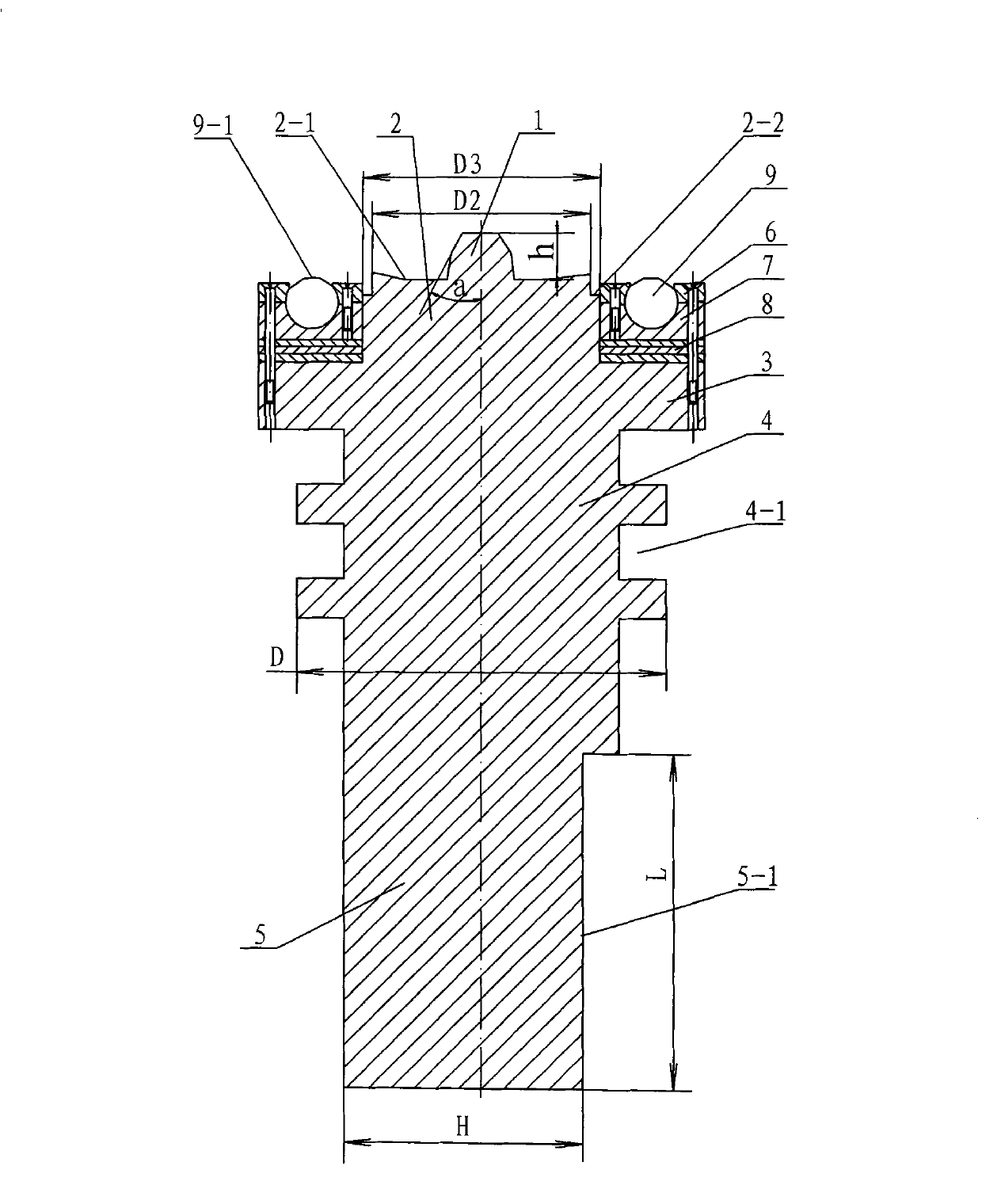
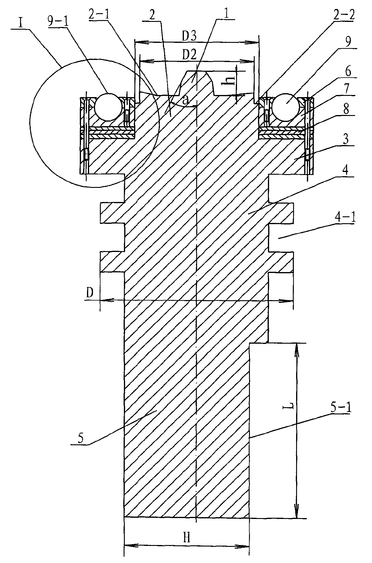
[0010] Specific implementation mode one: combine Figure 1 ~ Figure 3 Describe this embodiment, this embodiment comprises stirring head, upper clamping body 6, lower clamping body 7, at least one spacer 8 and at least three evenly distributed rolling balls 9, stirring head is made up of stirring pin 1, shaft shoulder 2. The positioning shoulder 3, the cylinder 4 and the clamping body 5 are composed of the stirring needle 1, the shaft shoulder 2, the positioning shoulder 3, the cylinder 4 and the clamping body 5 are sequentially integrated from top to bottom, and the stirring needle 1 Located at the axis of the front end of the shaft shoulder 2, the clamping body 5 is provided with a clamping surface 5-1 to fit with the inner hole of the stirring spindle and locked with a fastening screw. The stirring needle 1 is a cone, and the shaft The upper end surface of the shoulder 2 is a concave shoulder surface 2-1 whose outer edge is higher than the center, the outer diameter of the u...

specific Embodiment approach 2

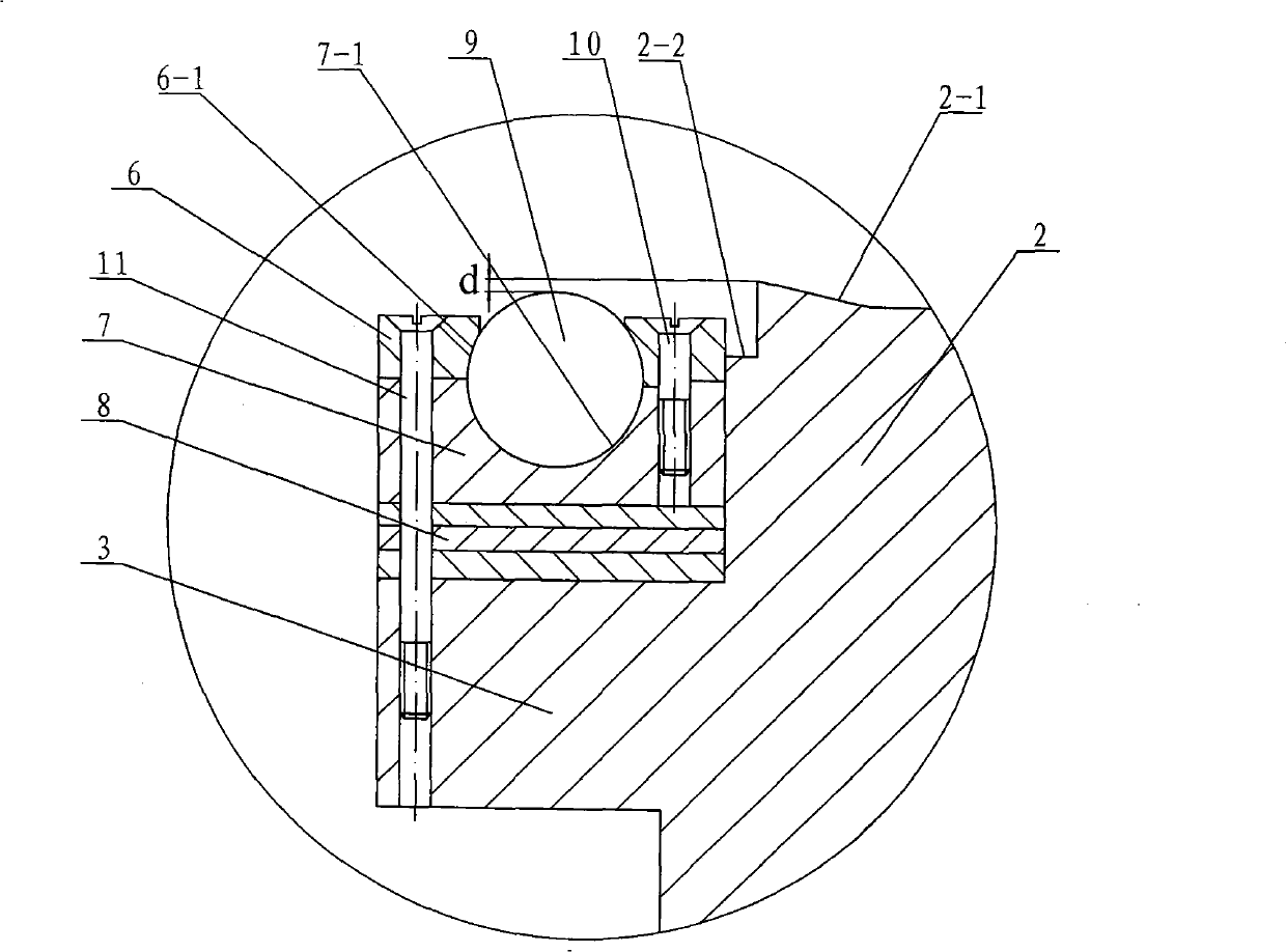
[0011] Specific implementation mode two: combination figure 1 and Figure 4 To illustrate this embodiment, the rolling surface 9-1 exposed outside the end surface of the upper clamping body 6 on the rolling ball 9 of this embodiment is a spherical surface or a plane processed into a smooth chamfer. Other components and connections are the same as those in the first embodiment.

specific Embodiment approach 3

[0012] Specific implementation mode three: combination figure 1 and Figure 4 To illustrate this embodiment, the number of rolling balls 9 in this embodiment is 3-8, the diameter of the rolling balls 9 is 5-12mm, and the spherical radian of the rolling surface 9-1 is 90°-150°. This is designed to prevent the carbide ball from falling out. A single rolling ball 9 is positioned, and there is no mutual interference between rolling balls 9 and rolling balls 9 . Other components and connections are the same as those in the first embodiment.


PUM

PropertyMeasurementUnit
diameteraaaaaaaaaa
thicknessaaaaaaaaaa

Abstract

The invention relates to a welding tool, in particular to a stirring friction welding tool capable of welding with rolling, solving the problem that the prior stirring friction welding line has residuThe invention relates to a welding tool, in particular to a stirring friction welding tool capable of welding with rolling, solving the problem that the prior stirring friction welding line has residurface of the lower clamping body. The stirring friction welding tool capable of welding with rolling utilizes the rolling balls uniformly distributed around the transition shoulder to weld a weldingsurface of the lower clamping body. The stirring friction welding tool capable of welding with rolling utilizes the rolling balls uniformly distributed around the transition shoulder to weld a weldingline and a near-welding region while rolling, realizes the conversion of surface tension on the surface of the welding line to comprehensive stress, controls the welding deformation, eliminates the s line and a near-welding region while rolling, realizes the conversion of surface tension on the surface of the welding line to comprehensive stress, controls the welding deformation, eliminates the scrap rubber at both sides of the welding line and further refines particles on the surface of the welding line.crap rubber at both sides of the welding line and further refines particles on the surface of the welding line.al stress, welding deformation and scrap rubber. A mixing needle is conical, the upper end surface of a shaft shoulder is a concave shaft shoulder surface with an outer edge higher than the center, anal stress, welding deformation and scrap rubber. A mixing needle is conical, the upper end surface of a shaft shoulder is a concave shaft shoulder surface with an outer edge higher than the center, and the outside diameter of the upper end of the shaft shoulder is provided with a transition shoulder; at least two gaskets and a lower clamping body are arranged on the upper end surface of the positid the outside diameter of the upper end of the shaft shoulder is provided with a transition shoulder; at least two gaskets and a lower clamping body are arranged on the upper end surface of the positioning shoulder from bottom to top, the upper end surface of the lower clamping body is uniformly provided with at least three grooves matched with rolling balls, and a rolling ball is mounted in a grooning shoulder from bottom to top, the upper end surface of the lower clamping body is uniformly provided with at least three grooves matched with rolling balls, and a rolling ball is mounted in a groove; an upper clamping body is uniformly provided with spherical holes which are matched with the rolling balls and correspond to the grooves, and the upper clamping body is arranged on the upper endove; an upper clamping body is uniformly provided with spherical holes which are matched with the rolling balls and correspond to the grooves, and the upper clamping body is arranged on the upper endsu

Description

technical field [0001] The invention relates to a welding tool, in particular to a combined friction stir welding tool used for rolling the weld seam and the near seam area during the friction stir welding process. Background technique [0002] Friction stir welding (FSW) is a new solid-phase joining method invented by the British Welding Institute (TWI) in 1991, and its working principle is as described in patents US5460317 and US5813592. In the process of friction stir welding, the friction between the high-speed rotating stirring head and the workpiece is used to generate heat to locally plasticize the welded material. When the stirring head moves forward along the welding interface, the plasticized material is stirred by the friction of the stirring head. The front of the head moves to the rear, and forms a dense solid-phase weld under the extrusion of the stirring head. Although compared with traditional fusion welding, friction stir welding has lower heat input and ex...

Claims


Application Information

Patent Timeline
Patent Type & Authority Patents(China)
IPC IPC(8): B23K20/12B29C65/06
Inventor 黄永宪张会杰刘会杰周利沈俊军
Owner HARBIN INST OF TECH
Why Eureka
Try Eureka