
Device for retaining a boot on a gliding, rolling, or walking board adapted to a sporting activity, and the boot therefor

Inactive Publication Date: 2005-03-03
SALOMON SA
View PDF31 Cites 0 Cited by
  • Summary
  • Abstract
  • Description
  • Claims
  • Application Information

AI Technical Summary

Benefits of technology

[0011] An object of the present invention is to reduce the frequency and / or the amplitude of the aforementioned displacements.
[0015] As a result of the friction-increasing structure according to the invention, i.e., whereby the friction between the boot and the retaining device is increased compared to the friction between the boot and the retaining device without such structure, the boot sole tends to remain in support on the base. Therefore, the boot upper tends to remain immobile with respect to the device. Consequently, the small displacements of the boot within its retaining volume on the device are reduced. This advantageously makes the steering of the board more accurate.

Problems solved by technology

However, it has been found that during steering, the boot makes small displacements within its retention volume on the device.
These small displacements hinder the accuracy of the steering of the board.

Method used


Image

  • Device for retaining a boot on a gliding, rolling, or walking board adapted to a sporting activity, and the boot therefor
  • Device for retaining a boot on a gliding, rolling, or walking board adapted to a sporting activity, and the boot therefor
  • Device for retaining a boot on a gliding, rolling, or walking board adapted to a sporting activity, and the boot therefor

Examples


first embodiment

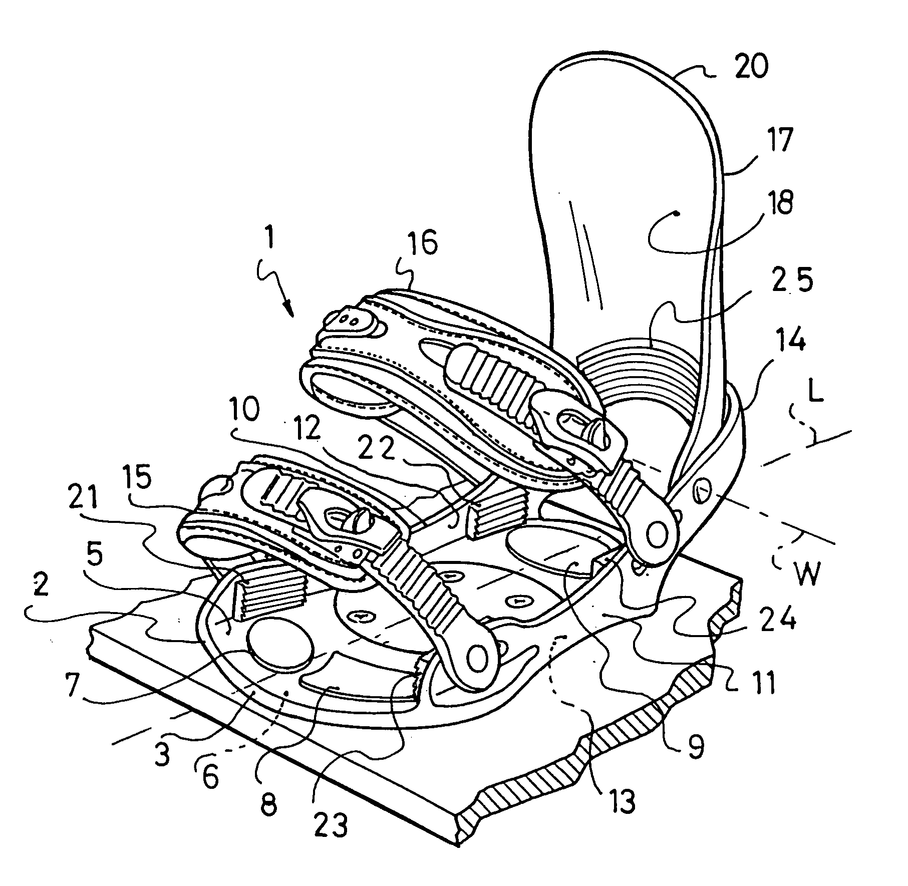
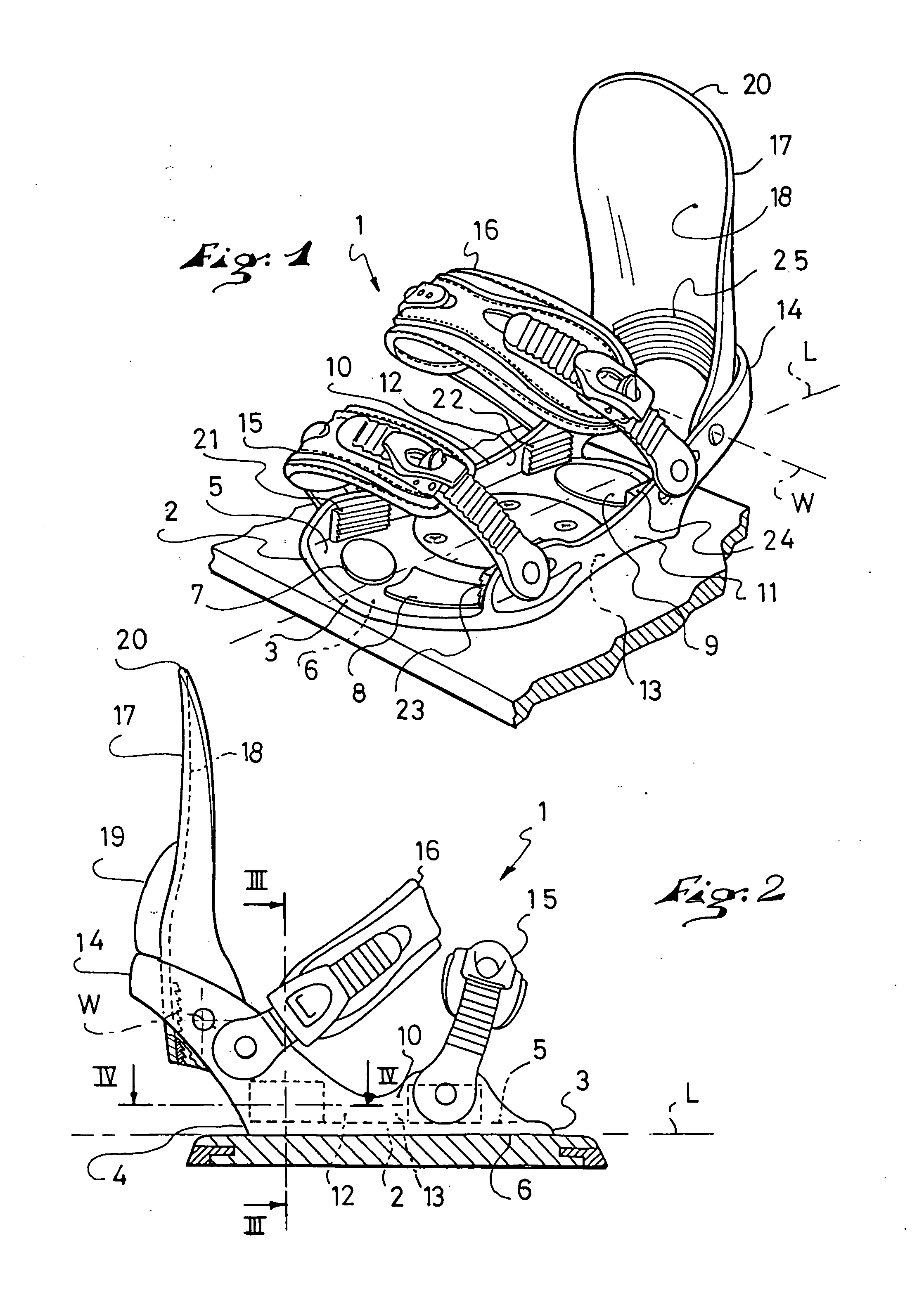
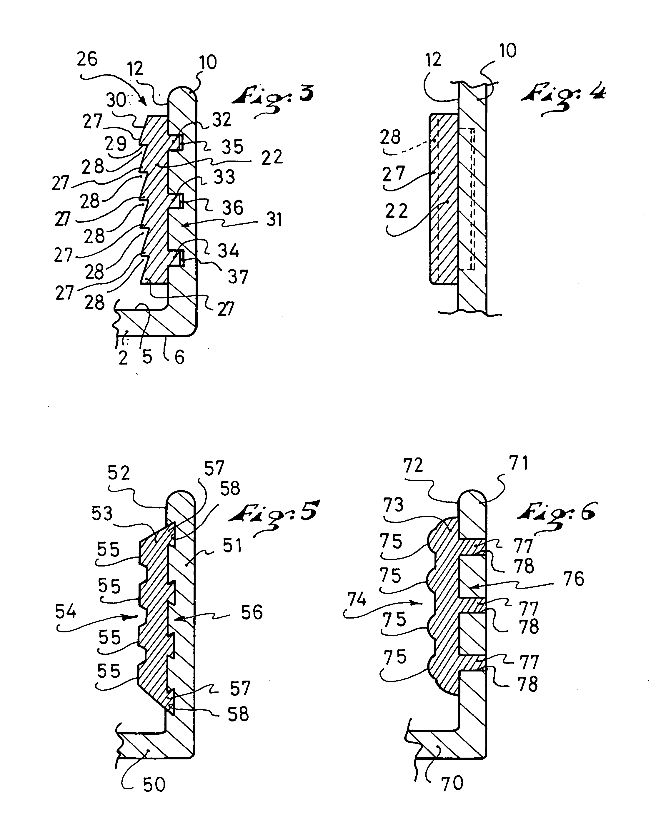
[0026] The first embodiment is described hereinafter with reference to FIGS. 1-4.

[0027] A device 1 for retaining a boot on a board is shown in perspective in FIG.

[0028] For reasons of convenience, the boot is not shown, although its position with respect to the retention device is readily apparent to those skilled in the art.

[0029] In a known manner, the device 1 includes a base 2 provided to receive at least partially the sole of a boot. The base 2 has a front end 3 and a rear end 4 which demarcate its length, along a longitudinal direction L of the device 1. The base 2 has an upper surface 5 provided to be opposite the sole, as well as a lower surface 6 provided to be opposite the board.

[0030] The longitudinal direction L of the device 1 is the same as that of the boot, when the latter is retained on the device 1.

[0031] Preferably, the base 2 is provided with front pads 7, 8 and a rear pad 9 which project, respectively, in relation to the upper surface 5. Each pad 7, 8, 9 is a...

second embodiment

[0058] For the second embodiment, as seen in FIG. 5, a base 50 is extended upward by an edge 51. An inner surface 52 of the edge 51 receives a friction plate 53. The latter has a friction surface 54 having a trapezoidal toothing, whose teeth 55 are substantially parallel to the base 50. An affixation surface 56 of the plate 53 and the edge 51 have dovetail tenons 57 and cutouts 58, respectively, for assembly with one another.

third embodiment

[0059] For the third embodiment, as seen in FIG. 6, a base 70 is extended upward by an edge 71. An inner surface 72 of the edge 71 receives a friction plate 73. The latter has a corrugated friction surface 74, whose projecting portions 75 are substantially parallel to the base 70. An affixation surface 76 of the plate 73 and the edge 71 have ribs 77 and grooves 78, respectively, for assembly with one another.


PUM


Abstract

A device for retaining a boot on a board adapted to a sporting activity, and a boot therefor. The device includes a base, a lateral edge, a rear support element, and at least one linkage for holding the boot above the base. The edge and the rear support element each have an inner surface. One or several of the inner surfaces of the device has at least one friction plate that projects at least partially with respect to the inner surface, the friction plate being provided at least to oppose a movement of the boot in relation to the base.

Description

CROSS-REFERENCE TO RELATED APPLICATIONS [0001] This application is a continuation of U.S. patent application Ser. No. 09 / 968,949, filed on Oct. 3, 2001, the disclosure of which is hereby incorporated by reference thereto in its entirety, and the priority of which is hereby claimed under 35 U.S.C. §120. [0002] This application is based upon French Patent Application No. 00 13032, filed Oct. 6, 2000, the disclosure of which is hereby incorporated by reference thereto in its entirety, and the priority of which is hereby claimed under 35 U.S.C. §119.BACKGROUND OF THE INVENTION [0003] 1. Field of the Invention [0004] The present invention relates to the field of devices for retaining a boot on a gliding, rolling, or walking board adapted to a sporting activity, as well as to a boot adapted to be retained by the device. [0005] 2. Description of Background and Relevant Information [0006] Devices of the aforementioned type are used in snowboarding, skiing, skateboarding, roller skating, sno...

Claims


Application Information

Patent Timeline
IPC IPC(8): A43B5/04A63C10/04A63C10/06A63C10/18A63C10/24A63C10/28
CPCA43B5/0403A43B5/0423A63C10/04A63C10/285A63C10/18A63C10/24A63C10/06
Inventor GONTHIER, JEAN-FRANCOIS
Owner SALOMON SA
Learn More