Circuit and method of operation for an adaptive charge rate power supply

a technology of charge rate and power supply, applied in the direction of liquid/fluent solid measurement, instruments, transportation and packaging, etc., can solve the problems of limited capacity, inability to find a replacement, aggravating the problem, etc., to minimize charge time, minimize charge time, and maximize current drawn

Inactive Publication Date: 2005-03-03
MALIKIE INNOVATIONS LTD
View PDF25 Cites 25 Cited by
  • Summary
  • Abstract
  • Description
  • Claims
  • Application Information

AI Technical Summary

Benefits of technology

It is therefore an object of the invention to provide a novel method and apparatus which allows standard battery charge controllers to be supplied from standard computer data ports and other power sources, which obviates or mitigates at least one of the disadvantages of the prior art.
One aspect of the invention is broadly defined as a battery charging circuit which adjusts to the parameters of an external power supply, to minimize charge time, comprising: a battery charge controller connected to the external power supply and electrifying a battery; and a regulating circuit for maximizing the current drawn by the battery charge controller, while keeping the voltage to the battery charge controller above a preset minimum limit, the preset minimum limit corresponding to a low voltage shut off level for the battery charge controller.
Another aspect of the invention is broadly defined as a method for charging a battery of a portable device via an external power supply, which adjusts to the parameters of the external power supply to minimize charge time, the method comprising the steps of: connecting a battery charge controller to the external power supply and to a rechargeable battery in the portable device; determining a low voltage shut off level for the battery charge controller; monitoring the voltage that the external power supply provides to the battery charge controller; and maximizing the current drawn by the battery charge controller, while keeping the voltage to the battery charge controller above the low voltage shut off level for the battery charge controller.

Problems solved by technology

Unfortunately, most of these battery charge controllers are designed to draw from a high capacity power supply with a steady voltage that will not sag appreciably under its current demands.
This is a problem when one attempts to use a power supply with limited capacity or when the power is delivered via unknown length and gauge of power wires (the resistance of such power wires cause a voltage drop which aggravates the problem).
Some computer data buses such as USB (universal serial bus) buses can be used to provide power to external devices, but while such power supplies are very convenient, they have limited capacity and are delivered via standard USB cables whose power wires could vary in length and gauge (anywhere from 20 AWG-28 AWG, for example).
As well, USB ports are able to supply limited power to a connected device.
A traveller who forgets his AC power supply at home, may not be able to find a replacement.
Unfortunately, USB ports can only provide limited power, while typical battery charge controllers are designed to receive a steady, high capacity power supply (that is, the input voltage at the battery charge controller is at or near its designed value, and does not drop as charging current increases).
This low voltage will cause many standard battery charge controllers to either shut down, or to simply oscillate and fail to charge the battery in the portable device 18 efficiently.
True, new dedicated battery charge controllers could be developed which are operable with the limited USB power supply and resistance of the cable and connector system, but that would be an expensive and complicated solution.
Such a design would become even more complicated to be compatible with both computer data bus power supplies and other power sources, such as AC power supplies.

Method used


Image

  • Circuit and method of operation for an adaptive charge rate power supply
  • Circuit and method of operation for an adaptive charge rate power supply
  • Circuit and method of operation for an adaptive charge rate power supply

Examples


comparator embodiment

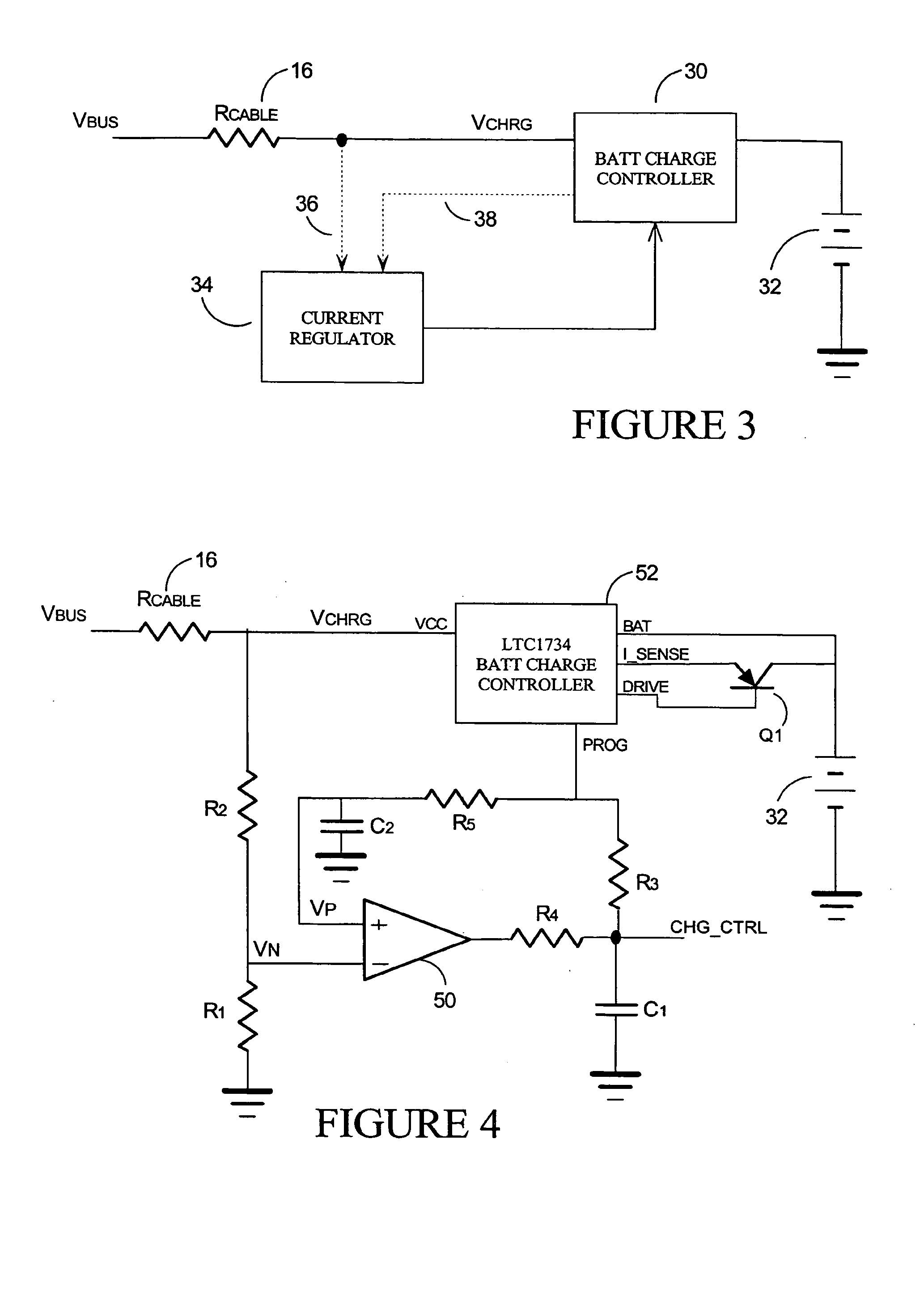
FIG. 4 presents an electrical schematic diagram charging circuit which employs two main components: a comparator 50 and a LTC1734 battery charge controller 52 having a current control pin PROG. Varying the current drawn through the control pin PROG will vary the current supplied by the LTC1734 battery charge controller 52 to the battery 32. Drawing more current out of the PROG pin will increase the charge current, while reducing the PROG current will reduce the charge current.

Many battery charge controllers have a similar current control system, but this embodiment will be described with respect to the LTC1734 controller. The LTC1734 controller can be operated in either constant current mode, or constant voltage mode.

In the constant voltage mode (entered when the charge voltage of the battery 32 reaches 4.2 VDC externally), the LTC1734 controller 52 servos its DRIVE pin to maintain its BAT pin at 4.2 VDC. In this mode, the current provided by the LTC1734 controller 52 will neces...

embodiment

Digital Potentiometer Embodiment

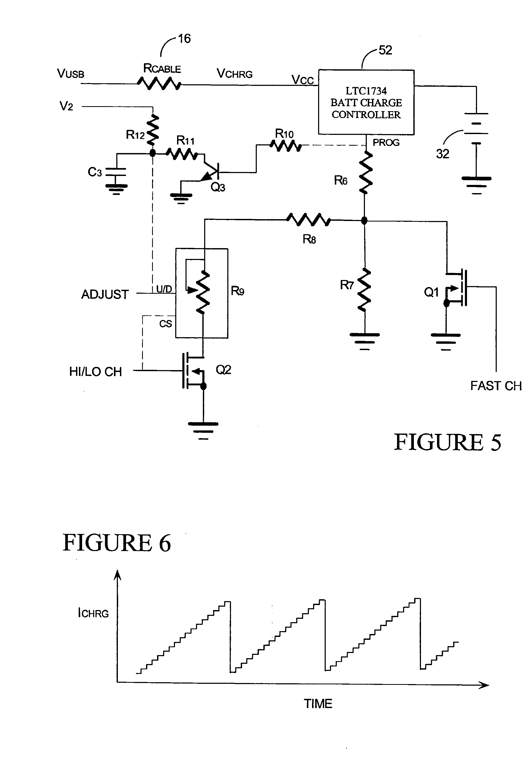
The invention is not strictly limited to the case where the low voltage threshold is never exceeded. In the embodiment of FIGS. 5 and 6, for example, the low voltage threshold could be exceed with each periodic cycle of current ramping, but the duty cycle still be sufficient to charge the battery. The only difficulty with such a circuit is that it would be necessary to reset the battery charge controller with each cycle. The circuit of FIGS. 5 and 6 ramps through a range of current supply, but uses a reset circuit to stop the ramping before the low voltage threshold is exceeded.

Like the embodiment of FIG. 4, this circuit uses the LTC1734 battery charge controller 52, though other battery charge controllers having a current control pin PROG could also be used. However, rather than having a comparator circuit as in FIG. 4 which modulates the current draw to avoid the low voltage shut off, this circuit ramps from a low current level, through to a high...


PUM


Abstract

A convenient source of charging power for portable communication devices is an integral power node of a computer data bus, such as a USB (universal serial bus) port. Unfortunately, USB ports have limited power capacity, making them generally incompatible with battery charge controllers (BCCs) which are designed to receive a steady, high capacity input. The invention provides a battery charging circuit which adjusts to the parameters of an external power supply such as a USB port by adding a regulating circuit to a standard BCC design. This regulating circuit maximizes the current drawn by the BCC, while keeping the voltage to the BCC above a preset minimum (the low voltage shut off level for the BCC). If the voltage to the BCC begins to drop, the regulating circuit reduces the current drawn, so the voltage rises and stays within the operating range of the BCC.

Description

This invention relates in general to battery chargers, and more specifically to a method and apparatus for charging a battery in a portable communication device from a variety of power sources, including limited capacity sources such as an integral power node of a computer data bus. One such computer data bus would be a USB (universal serial bus) port. BACKGROUND OF THE INVENTION With the current computing and information revolution, portable electronic devices such as cellular telephones, personal digital assistants (PDAs), digital pagers and wireless email devices, are becoming very common. These portable devices are typically powered by internal batteries which must be recharged periodically by an external power source, using a battery charger. Battery chargers generally receive power from a standard AC electrical outlet and convert the AC power into a low DC voltage for recharging a battery. The battery chargers of these portable devices also generally employ a “battery char...

Claims


Application Information

Patent Timeline
Patent Type & Authority Applications(United States)
IPC IPC(8): G06F1/26H02J7/00
CPCG06F1/266H02J7/0055H02J7/0093H02J7/008H02J7/0073H02J2207/40H02J7/00711H02J7/0071H02J7/007182
Inventor VESELIC, DUSANHABICHER, MICHAEL F.IDZIK, JACEK S.MALTON, JONATHAN T.
Owner MALIKIE INNOVATIONS LTD
Why Eureka
Try Eureka