Color misregistration reducer
- Summary
- Abstract
- Description
- Claims
- Application Information
AI Technical Summary
Benefits of technology
Problems solved by technology
Method used
Image

Examples
Example
FIRST EMBODIMENT
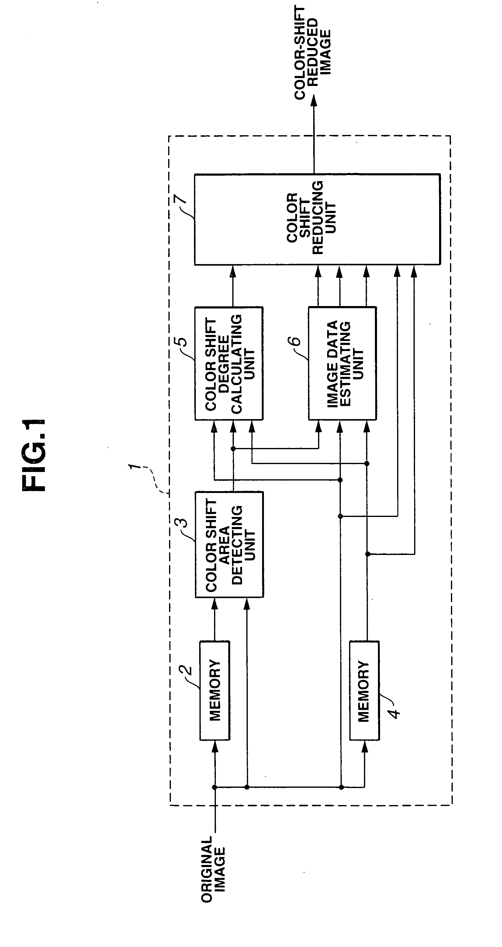
[0016] Referring to FIG. 1, a color shift reducing apparatus 1 comprises: a memory 2 for delaying an input image signal; a color shift area detecting unit 3 for detecting an area in which color shift occurs on the basis of input image data and image data delayed through the memory 2; a memory 4 for delaying the input image data by one field; a color shift degree calculating unit 5 for calculating data indicating the degree of color shift on the basis of a color shift detection signal output from the color shift area detecting unit 3, the input image data, and the image data delayed through the memory 4; an image data estimating unit 6 for estimating image data on the basis of the color shift detection signal output from the color shift area detecting unit 3, the input image data, and the image data delayed through the memory 4; and a color shift reducing unit 7 for forming a color shift reduced image on the basis of the image data output from the memory 4, estimated...
Example
SECOND EMBODIMENT
[0069] Referring to FIG. 11, the structure of a color shift reducing apparatus 23 according to the present embodiment is substantially the same as that of the color shift reducing apparatus according to the first embodiment excluding the supply of a color shift reduced image to a color shift area detecting unit 24, the internal structure of a color shift degree calculating unit 25, the internal structure of an image data estimating unit 26, and the internal structure of a color shift reducing unit 27. Accordingly, the difference therebetween will now be described. The same components are designated by the same reference numerals to omit the description of the same components.
[0070] Referring to FIG. 12, the color shift area detecting unit 24 comprises: an RGB matrix circuit 28 for calculating color signals Cr and Cb and a brightness signal Y from input image data of RGB and a color shift reduced image processed through the color shift reducing unit 27 and then out...
Example
THIRD EMBODIMENT
[0105] Referring to FIG. 20, a color shift reducing apparatus 37 according to the present embodiment comprises: a memory 38 for delaying an input image by one field; and a color shift area detecting unit 39 for detecting color shift on the basis of the image data delayed by one field, the data being supplied from the memory 38, the input image data of the color shift reducing apparatus 37, and a color shift reduced-image output from the color shift reducing unit 27. The other components are the same as those in the color shift reducing apparatus according to the second embodiment. A difference between the construction of the apparatus according to the third embodiment and that according to the second embodiment will now be described. The same components are designated by the same reference numerals to omit the description thereof.
[0106] Referring to FIG. 21, the color shift area detecting unit 38 comprises an RGB-YC matrix circuit 40 for calculating color signals C...
PUM
 Abstract
Description
Claims
Application Information
 - R&D Engineer
- R&D Manager
- IP Professional
- Industry Leading Data Capabilities
- Powerful AI technology
- Patent DNA Extraction
Browse by: Latest US Patents, China's latest patents, Technical Efficacy Thesaurus, Application Domain, Technology Topic.
© 2024 PatSnap. All rights reserved.Legal|Privacy policy|Modern Slavery Act Transparency Statement|Sitemap