Apparatus for disposal of toxic and radioactive waste

Inactive Publication Date: 2005-03-03
RODE CHRISTIAN STIG
View PDF16 Cites 8 Cited by
  • Summary
  • Abstract
  • Description
  • Claims
  • Application Information

AI Technical Summary

Benefits of technology

[0011] Previous mechanisms for sea-floor storage of waste have either buried materials to a lesser depth or required expensive drillin

Problems solved by technology

Previous mechanisms for sea-floor storage of waste have either buried materials to a lesser depth or required expensive drilling.
Such motors operate

Method used


Image

  • Apparatus for disposal of toxic and radioactive waste
  • Apparatus for disposal of toxic and radioactive waste
  • Apparatus for disposal of toxic and radioactive waste

Examples


Embodiment Construction

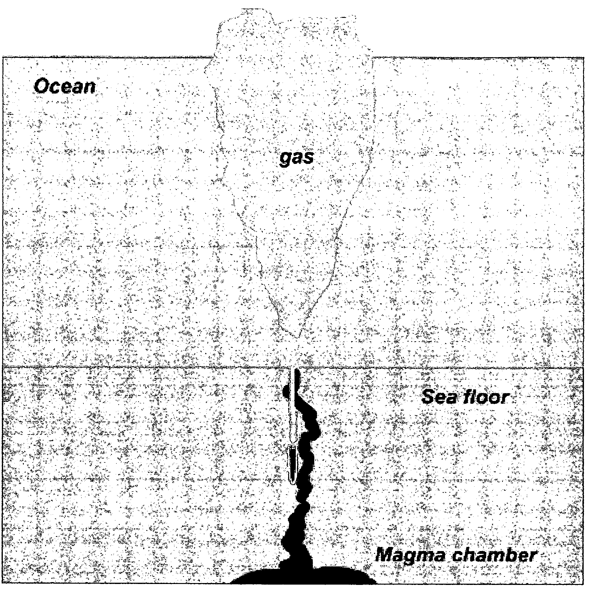
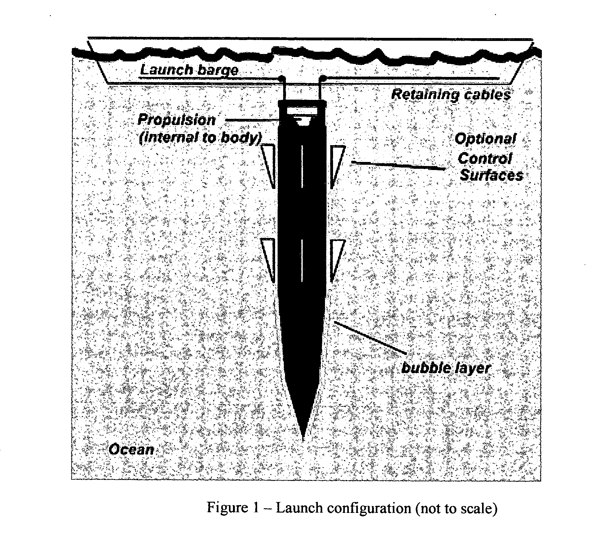
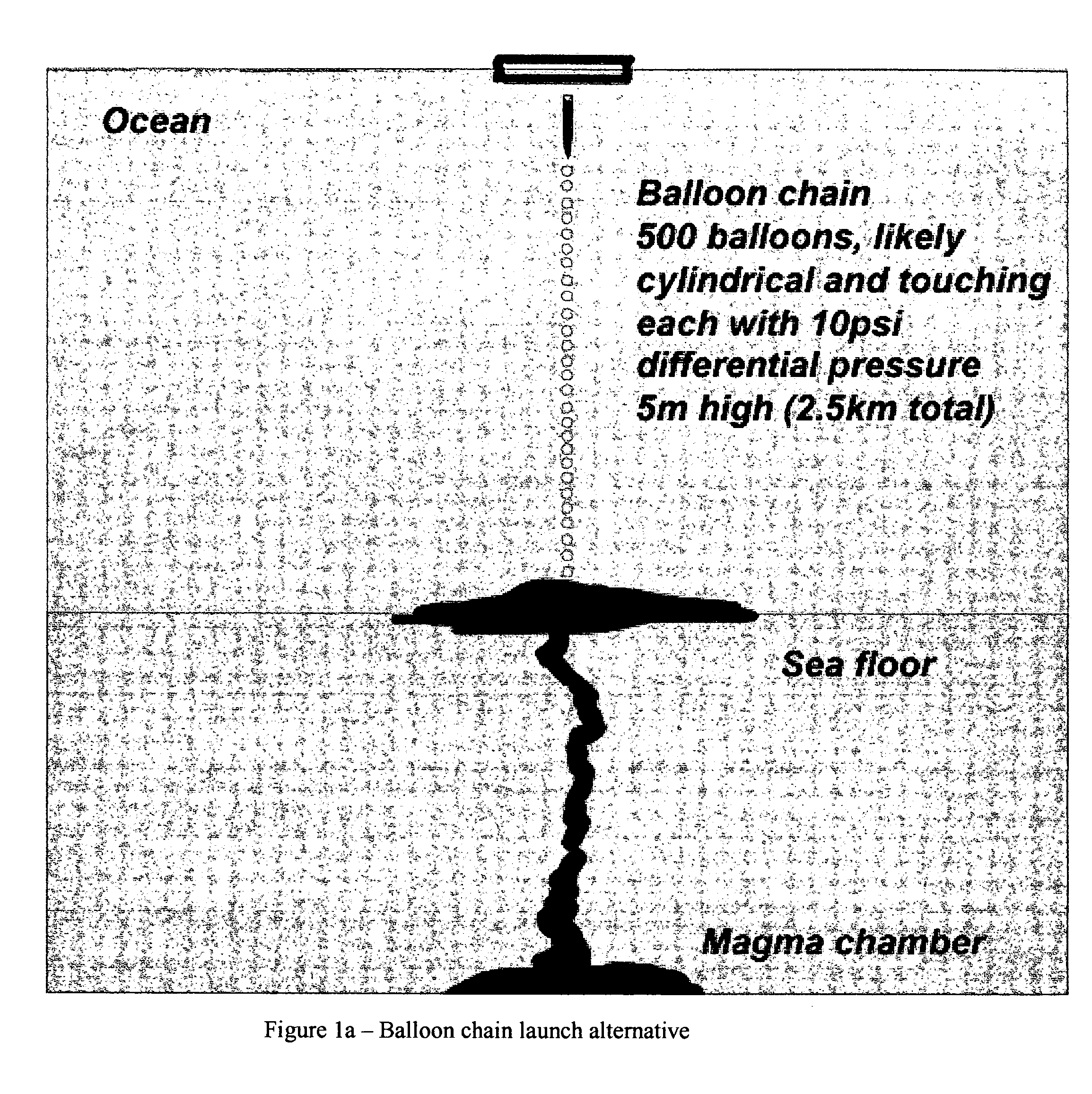
[0027] In the preferred embodiment, the projectile is a hollow metal “bullet” (i.e., a hollow rocket or arrow-shaped tapered cylinder) composed of any inexpensive material with good hardness, fracture resistance and, for subduction / volcanic applications, a melting point higher than basaltic lava with a drop weight of potentially thousands of tons, encapsulating an inner chamber with highly radioactive waste dissolved in a carrier material, such as depleted uranium, and / or vitrified within glass (e.g., borosilicate glass, silicon carbide, zirconium nitride) with high chemical inertness, radiation tolerance and, for subduction / volcanic applications, high melting point. For the sake of a concrete example, the preferred embodiment uses cast iron as the projectile material. Depleted uranium (DU, possibly alloyed with 0.75% Ti), however, would make an excellent projectile material, and as a bonus contribute to the disposal of this too-abundant material, however, its use would likely be co...


PUM


Abstract

A new system for underwater waste disposal is disclosed, consisting of a high-speed, hardened penetrator, optional rocket motor (or other compact propulsion device) and alternative mechanisms for eliminating water drag by surrounding the projectile with a gas layer.

Description

CROSS REFERENCE TO RELATED APPLICATIONS [0001] The present application claims benefit of Prov. Application 60 / 484,479, filed Jul. 2, 2004.STATEMENT REGARDING FEDERALLY SPONSORED RESEARCH OR DEVELOPMENT [0002] Not ApplicableREFERENCE TO A MICROFICHE APPENDIX [0003] None BACKGROUND OF THE INVENTION [0004] 1. Field of the Invention [0005] This invention relates to the fields of waste disposal and underwater rocketry. [0006] 2. Description of Prior Art [0007] Construction of containers intended for at-sea disposal of hazardous waste is a known art. For example, Quase, (U.S. Pat. No. 3,659,108) discloses a compressible container for deep-sea disposal of hazardous materials. Haynes, et al. (U.S. Pat. No. 4,377,509) discloses a container in which waste is packed in a wettable material which thereby becomes incompressible. [0008] It is preferable to bury such materials beneath the nominal ocean floor, for example, in pelagic clay sediments or the deep terrigenous sediments that accumulate n...

Claims


Application Information

Patent Timeline
IPC IPC(8): B09B1/00B65G5/00
CPCB09B1/002G21F9/32B65G5/00
Inventor RODE, CHRISTIAN STIG
Owner RODE CHRISTIAN STIG
Why Eureka
Try Eureka