Portable tennis backboard

a tennis backboard and tennis technology, applied in the field of tennis backboards, can solve the problems of insufficient space, small structure, large backboards, etc., and achieve the effect of optimal weight distribution and minimizing the chance of being tipped over by acciden

Inactive Publication Date: 2005-03-03
CHANG MICHAEL C +1
View PDF10 Cites 12 Cited by
  • Summary
  • Abstract
  • Description
  • Claims
  • Application Information

AI Technical Summary

Benefits of technology

[0012] Each reflecting surface is stiffened in the anterior-posterior plane by the above-described stiffening gussets, which run substantially the entire vertical length of the reflecting surface on the posterior aspect of the reflecting surface, and from the base up to a distance not greater than about 36″ from the base on the anterior surface, i.e., below the net simulating stripe. Thus, a pair of stiffening gussets generally are half the depth of the base and are attached at the rear of the reflecting surface. Another pair of shorter gussets not usually higher than 36″ from the base are attached at the front of the reflecting surface; one gusset along each side edge of the reflecting surface of the module. At its base, the width of the gusset is about one-half the depth of the base. The stiffening gussets are edge-joined to the reflecting surface and provide torsional stiffness by virtue of the continuous edge joint. The joining can be by any suitable means such as typical connectors (e.g. screws) or adhesive or both. A reflecting surface is stiffened in the medial-lateral dimensions by the continuous edge-joint which attaches the reflecting surface to the base below the net stripe, and by a stiffener that runs the width of the reflecting surface at the top of the reflecting surface. This stiffener is edge-joined to the top or superior posterior edge of the reflecting surface only, to prevent aberrant reflection of the ball.
[0014] An important feature of the design is that the weight of the reflecting surface is centered in both horizontal directions over the base to minimize the chance of being tipped over by accident. Furthermore, the tapered shape of the gussets located at the rear sides of the playing surface allows for optimal weight distribution as well, with the majority of the weight being low near the base.

Problems solved by technology

These backboards, however, are usually large and difficult to maneuver.
Or the structures are small and do not allow adequate space for practicing tennis strokes.

Method used


Image

  • Portable tennis backboard
  • Portable tennis backboard
  • Portable tennis backboard

Examples


Embodiment Construction

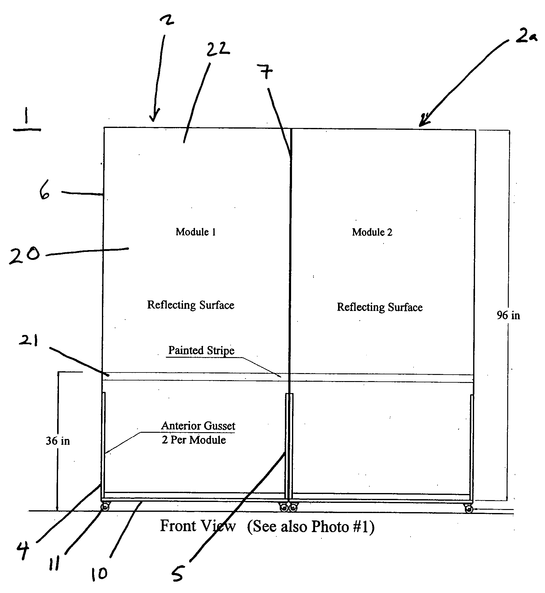
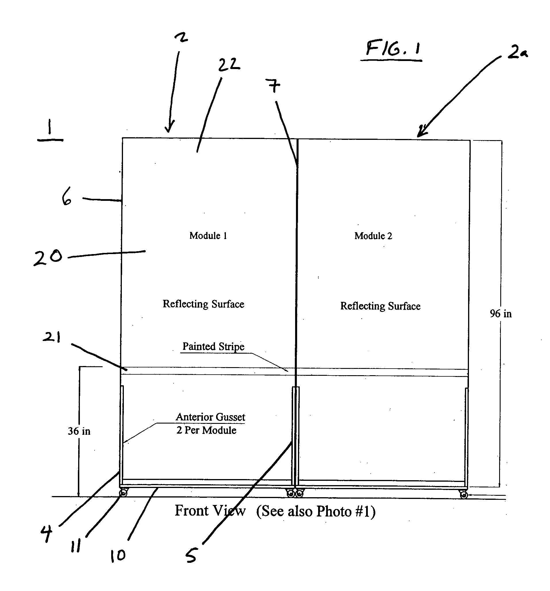
[0022]FIG. 1 depicts a front elevation view of a portable tennis backboard (1) of modular construction that is freestanding. The depicted embodiment demonstrates a portable tennis backboard (1) formed from a first module (2) and a second module (2a), which are each approximately four feet wide and eight feet high. However, different sizes of modules can be utilized. The modules can be constructed from a variety of materials, such as wood, fiberglass, synthetic materials, metal, and a variety of combinations thereof.

[0023] The depicted embodiment shows a first anterior gusset (4) and a second anterior gusset (5) attached to the reflecting surface (20) of module 1. In the depicted embodiment, the first anterior gusset (4) and the second anterior gusset (5) are attached to the lateral edge (6) and medial edge (7) of the reflecting surface (20), which has a tennis net height indicator (21) formed approximately 36 inches above ground level on the front side (22) of the reflecting surfac...


PUM


Abstract

A portable tennis backboard that can be made to be foldable and formed by two vertical modules.

Description

BACKGROUND OF THE INVENTION [0001] The use of a wall, or any suitable substantially vertical surface, to hit tennis strokes against enables a player to practice by himself or herself. Such a surface used for practicing strokes is commonly referred to as a “backboard,” and is used by tennis players to improve the form and consistency of their game. Usually lines are painted on the backboard to indicate the top and center strap of the net, that is, where the top and center strap would be if the backboard were actually a net on a tennis court. Most backboards are planar and nominally vertical structures, but variant designs can employ slanted, curved, or uneven surfaces so that the ball comes off at various angles or with various types of spin. Present-day backboards have been engineered to be much quieter than those of the past through the use of fiberglass and plastics such as Styrofoam. Although backboards have in the main been used for practicing tennis, with suitable modifications...

Claims


Application Information

Patent Timeline
Patent Type & Authority Applications(United States)
IPC IPC(8): A63B69/00A63B69/38
CPCA63B69/0097A63B2210/50A63B2071/025A63B69/38
Inventor CHANG, MICHAEL C.MOORE, HAROLD D.
Owner CHANG MICHAEL C
Why Eureka
Try Eureka