Prosthesis for partial replacement of an articulating surface on bone

a technology for articulating surfaces and bone, applied in the field of prosthesis for partial replacement of articulating surfaces on bone, can solve the problems of joint dysfunction, injury to movable joints, difficulty in repair,

Inactive Publication Date: 2005-03-03
MAYO FOUND FOR MEDICAL EDUCATION & RES
View PDF95 Cites 136 Cited by
  • Summary
  • Abstract
  • Description
  • Claims
  • Application Information

AI Technical Summary

Problems solved by technology

Injury to a movable joint may be difficult to repair.
In particular, the injury may damage one or more of the articulating surfaces that slide on one another to define movement of opposing bones at the joint.
If the shape and position of the damaged articulating surface are not reconstructed accurately, the joint may not function properly.
Accordingly, movement of the opposing bones may be limited, unnatural, and/or painful after inaccurate repair of the damaged articulating surface.
For example, the total prosthesis may be difficult to position accurately because native bone structures at the end of the bone are removed before the prosthesis is positioned.
As a result, native bone structures cannot be used for anatomic joint alignment.
Trauma to the elbow may disrupt articulation of the distal humerus with both of its partners, the proximal ulna and the radial head of the radius.
In particular, elbow trauma may dislocate the ulna posteriorly from the humerus, as a result of a fracture

Method used


Image

  • Prosthesis for partial replacement of an articulating surface on bone
  • Prosthesis for partial replacement of an articulating surface on bone
  • Prosthesis for partial replacement of an articulating surface on bone

Examples


example 1

Prosthesis for Partial Radial Head Replacement

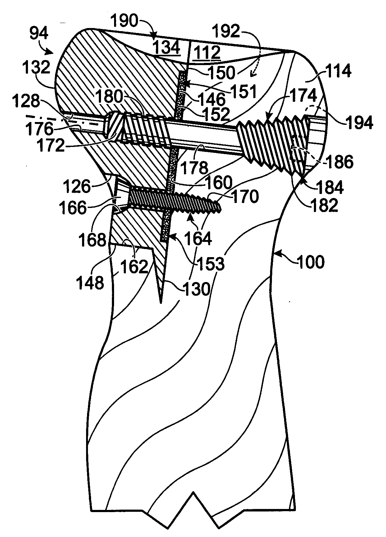
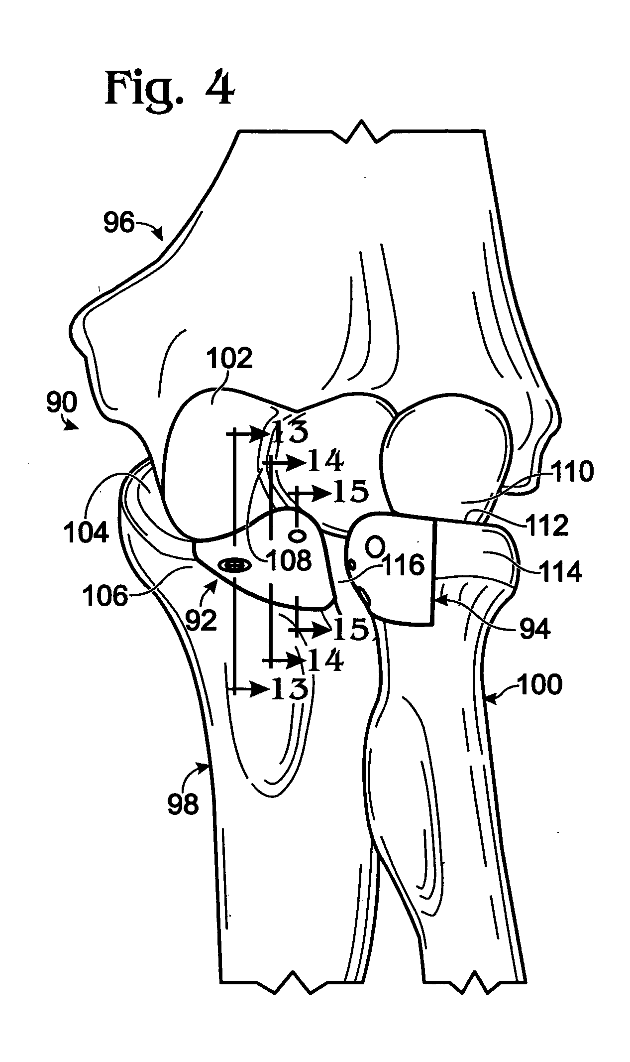
[0057] This example describes the structure and installation of exemplary partial radial head prosthesis 94; see FIGS. 4-8.

[0058]FIGS. 5-7 show partial radial head prosthesis 94 of FIG. 4 in isolation from the bones of left elbow 90. Partial radial head prosthesis 94 may include a body 120 having a proximal head 121 and a distal neck 122. The head and neck may define an outer surface 123 and an inner surface 124. The body also may define a plurality of openings or holes 126, 128 for receiving fasteners. A prong 130 may be connected to the body, for example, extending from a distal region of inner surface 124. In alternative embodiments, the prong may be a stem configured to extend into a natural bone cavity, such as the medullary canal.

[0059] Outer surface 123 may include a plurality of spaced surface regions 132, 134 for articulation with the ulna and the humerus, respectively. Lateral or side surface region 132 may be configured to ...

example 2

Prosthesis for the Coronoid Process

[0066] This example describes the structure and installation of exemplary coronoid prosthesis 92; see FIGS. 4 and 9-15.

[0067]FIGS. 9-12 show various views of coronoid prosthesis 92 in isolation from the bones of the left elbow. Coronoid prosthesis 92 may include a body 200 having a base 202 and a ridge 204 extending between opposing ends of the base. Body 200 may define an outer surface 206 and an inner surface 208. One or more prongs 210 or other projections may be connected to body 200 adjacent the inner surface, such that the projections may extend into the ulna when the prosthesis is installed.

[0068] Outer surface 206 may include distinct surface regions. Outer surface 206 may include an articulation or contact surface region 212 (see FIG. 9) for contact with trochlea 102 (see FIG. 4). Accordingly, articulation region 212 may be configured to approximate the articulation contour of a distal portion of the coronoid. Outer surface 206 also may...

example 3

Alternative Prosthesis for the Coronoid Process

[0075] This example describes the structure and installation of an alternative exemplary coronoid prosthesis; see FIGS. 16-18.

[0076]FIGS. 16 and 17 are views of an alternative coronoid prosthesis 230 that may be used in place of coronoid prosthesis 92. Coronoid prosthesis 230 may include a body 232, a tab 234 connected to the body, and one or more projections, such as prongs 236 extending from the body.

[0077] The body, the tab, and the projections may define an inner surface 238 and an outer surface 240. Inner surface 238 may include a lip 242 that extends partially or completely around a perimeter of the inner surface. Lip 242 may create a recessed region 244 central to the lip. The recessed region may be unfilled or filled (or coated) before installation of the prosthesis, as described above. In alternative embodiments, the lip may not be included in the prosthesis. Inner surface 238 may include a body inner surface 246 and a tab i...


PUM

PropertyMeasurementUnit
Adhesion strengthaaaaaaaaaa
Radiusaaaaaaaaaa
Perimeteraaaaaaaaaa

Abstract

Systems, including apparatus, methods, and kits, for replacing a portion of an articulating bone surface with a surface region of a partial prosthesis.

Description

CROSS-REFERENCE TO PRIORITY APPLICATION [0001] This application is based upon and claims the benefit under 35 U.S.C. § 119(e) of U.S. Provisional Patent Application Ser. No. 60 / 498,807, filed Aug. 28, 2003, which is incorporated herein by reference in its entirety for all purposes.BACKGROUND OF THE INVENTION [0002] Injury to a movable joint may be difficult to repair. In particular, the injury may damage one or more of the articulating surfaces that slide on one another to define movement of opposing bones at the joint. If the shape and position of the damaged articulating surface are not reconstructed accurately, the joint may not function properly. Accordingly, movement of the opposing bones may be limited, unnatural, and / or painful after inaccurate repair of the damaged articulating surface. [0003] A common surgical alternative for reconstruction of an injured joint involves insertion of a prosthesis. The prosthesis may be configured to replace all of an articulating surface on o...

Claims


Application Information

Patent Timeline
IPC IPC(8): A61F2/00A61F2/30A61F2/38A61F2/40A61F2/42
CPCA61F2/3804A61F2310/00964A61F2/4202A61F2/4225A61F2/4241A61F2/4261A61F2002/30616A61F2002/30711A61F2002/30713A61F2002/30714A61F2002/30909A61F2002/4007A61F2250/0086A61F2250/0087A61F2250/0089A61F2310/00017A61F2310/00023A61F2310/00029A61F2310/00203A61F2310/00293A61F2/4081A61F2002/3071
Inventor O'DRISCOLL, SHAWN W.MORREY, BERNARD F.
Owner MAYO FOUND FOR MEDICAL EDUCATION & RES
Why Eureka
Try Eureka