

Anti gas-lock pumping system
Inactive Publication Date: 2005-03-10
GALLANT RAYMOND DENIS
View PDF20 Cites 17 Cited by
- Summary
- Abstract
- Description
- Claims
- Application Information
AI Technical Summary
Benefits of technology
[0019] In an additional embodiment, the pump plunger may include at least one seal around its circumference for preventing fluid flow between the plunger and the pump barrel.
Problems solved by technology
In such a conventional pumping system, if gas is present in the well and fills the pumping chamber defined between the valves, it may cause gas-lock of the pump.
Subsequently, on upstroke, the pump has reduced efficiency, as gas remains in the chamber, preventing it from completely filling with fluid.
Over time, gas build-up may lead to gas-locking and failure of the pump.
One disadvantage of such systems is their reduced efficiency when the pump is not placed vertically, as the efficiency of travelling valves is generally reduced by positioning.
In addition, gas may not fully escape from the pumping chamber if the position is not vertical.
Further, such systems may alow pumped fluid to re-enter the pumping chamber as the gas is escaping.
Method used
View moreImage
Smart ImageViewing Examples

Examples
example
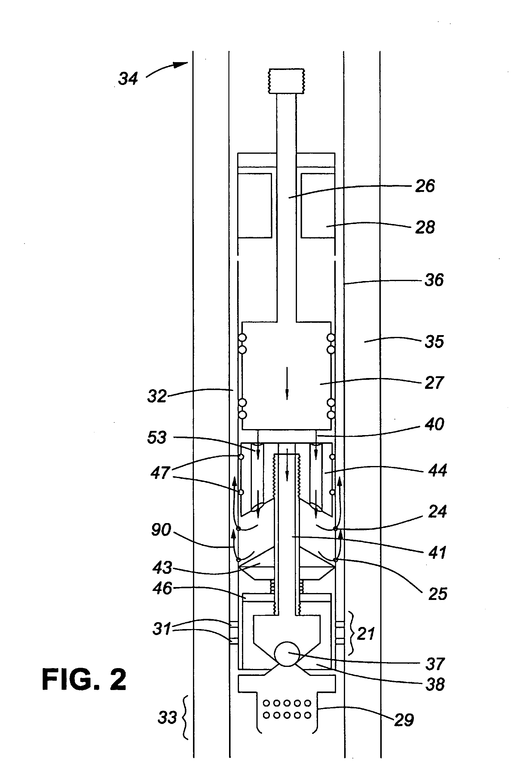
[0055] The anti gas-lock valve described above was placed within a pump into a downhole production well in Central Alberta, and was operated for 14 days. The pump produced 1000 L / h of oil, and maintained this efficiency for the entire duration of the test, indicating that the pump did not experience gas-lock. It was observed that both oil and gas were pumped into the annulus exterior of the pump barrel, to the top of the well. It was further evident that the entire contents of the pumping chamber was fully displaced with each downstroke of the plunger, this was also indicative that the pump would not be subject to gas locking.
Login to View More PUM
 Abstract
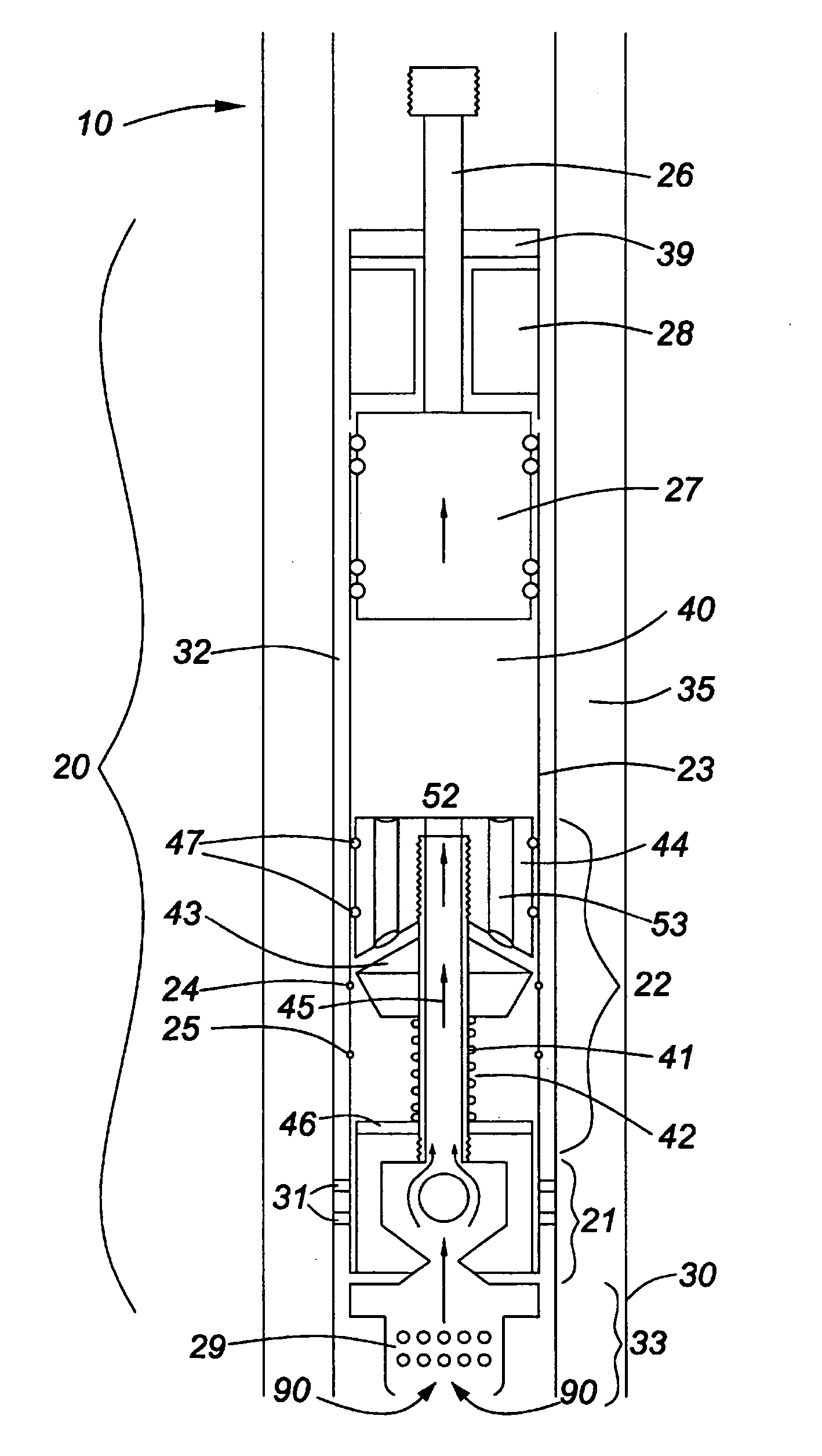
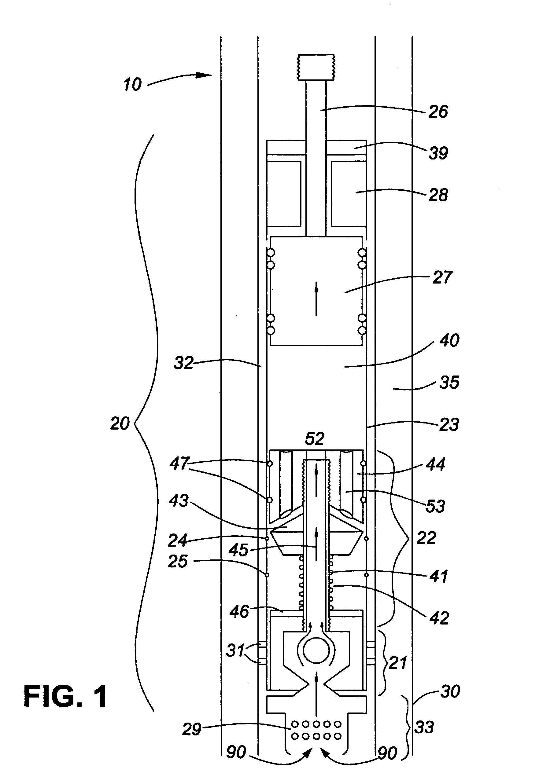
An improved fluid pumping system is described. The pump is designed such that any gas present in the fluid being pumped is completely displaced from the pumping chamber with each downstroke of a pump plunger. This prevents pump failure due to gas-locking by preventing gas build-up within the pump, thereby improving long-term pumping efficiency and increasing pump life.
Description
FIELD OF THE INVENTION [0001] The present invention relates to anti gas-lock fluid pumping systems, and more specifically, to a valve which prevents gas-locking of a downhole pump. BACKGROUND OF THE INVENTION [0002] Piston pumps are commonly used in many applications, such as the pumping of water, air, and other fluids. Piston pumps are well adapted for use in an oil well, as they have linear mechanical parts, are relatively simple in their operation, and are of a size and shape easily accommodated within a downhole well. [0003] Conventional downhole piston pumps have both a lower standing valve, and an upper travelling valve which is generally attached to the piston and plunger of the pump. During plunger upstroke, a pumping chamber is expanded, creating a negative pressure cavity. The negative pressure unseats the lower standing valve, allowing fluid from the well to be drawn into the pumping chamber. As the plunger is drawn up, the travelling valve is closed due to the build-up n...
Claims
Login to View More Application Information
Patent Timeline
 IPC IPC(8): F04B47/00F04B53/06F04B53/10
CPCF04B47/00F04B53/102F04B53/06
InventorGALLANT, RAYMOND DENIS
OwnerGALLANT RAYMOND DENIS