
Signaling in a mobile cellular communication network with pooled MSCs

a mobile cellular communication and network technology, applied in the field of mobile switching apparatus, can solve the problems of inefficient use of core network, increased difficulty, and inability to implement simple mechanism, and achieve the effect of efficient relaying of paging response messages

Inactive Publication Date: 2005-03-10
TELEFON AB LM ERICSSON (PUBL)
View PDF15 Cites 40 Cited by
  • Summary
  • Abstract
  • Description
  • Claims
  • Application Information

AI Technical Summary

Benefits of technology

[0028] In view of the above, a first object of the present invention is to achieve an efficient relay of paging response messages to related paging requests in a core network with pooled mobile switching centers.
[0029] A second object of the present invention is to achieve an efficient and flexible routing of signaling messages between a core network and an access network.

Problems solved by technology

However, this simple mechanism will not work in case the 1:n relationship between a mobile switching center MSC and related base station controllers BSC is generalized to a case where each base station controller may be served by a plurality of mobile station centers MSC to increase network capacity and reliability.
Nevertheless, this might be a pre-requisite to meet future service demands since for large mobile cellular communication networks a static link between access nodes and mobile switching centers MSC could turn out to be an inefficient way of using the core network.
The problems become even more difficult when mobile communication networks cover very large areas, e.g., spanning more than one time zone.
There exists no possibility to do load sharing over available mobile switching centers MSC to spread high load during peak hours in different time zones, e.g., between Dallas and Los Angeles.
Similar problems as outline above with respect to mobile terminal terminating signaling traffic also exist with respect to mobile terminal originating signaling traffic when access nodes have the choice to access different mobile switching centers MSC.
However, this approach requires the analysis of signaling messages to find subscriber identities and therefore introduces delays as possible bottlenecks.
Referring only to subscriber identities could decrease the scope of flexibility.
Further, when a mobile switching center is out of order related subscribers cannot receive signaling messages.

Method used


Image

  • Signaling in a mobile cellular communication network with pooled MSCs
  • Signaling in a mobile cellular communication network with pooled MSCs
  • Signaling in a mobile cellular communication network with pooled MSCs

Examples


Embodiment Construction

[0075] In the following, the best mode of carrying out the present invention as well as preferred embodiments thereof, further objects and further advantages will be explained with respect to the drawing. Insofar as different features of the present invention are explained with respect to certain aspects thereof, it is understood that these features are combinable with each other to achieve various other modifications and variations of the present invention.

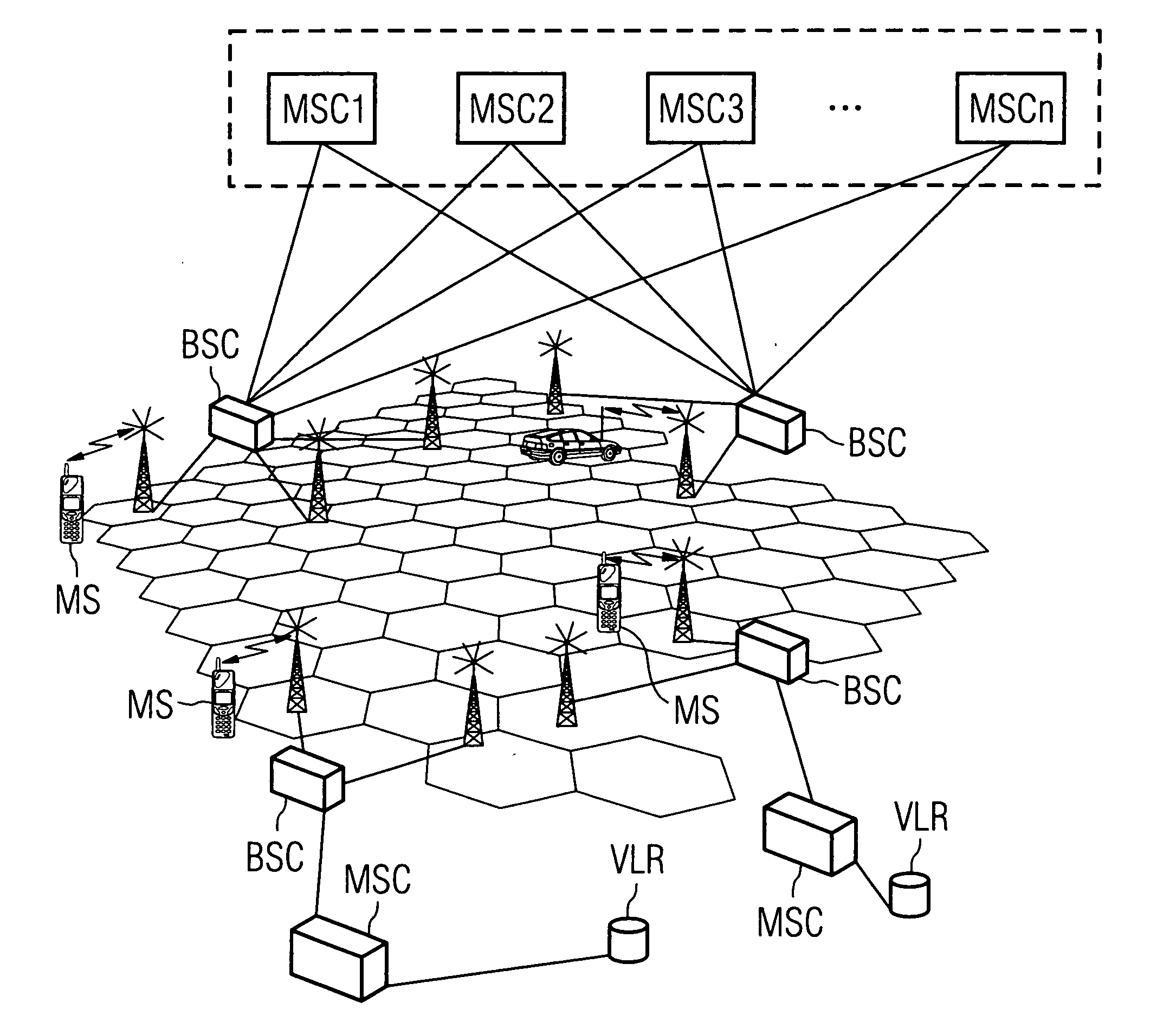
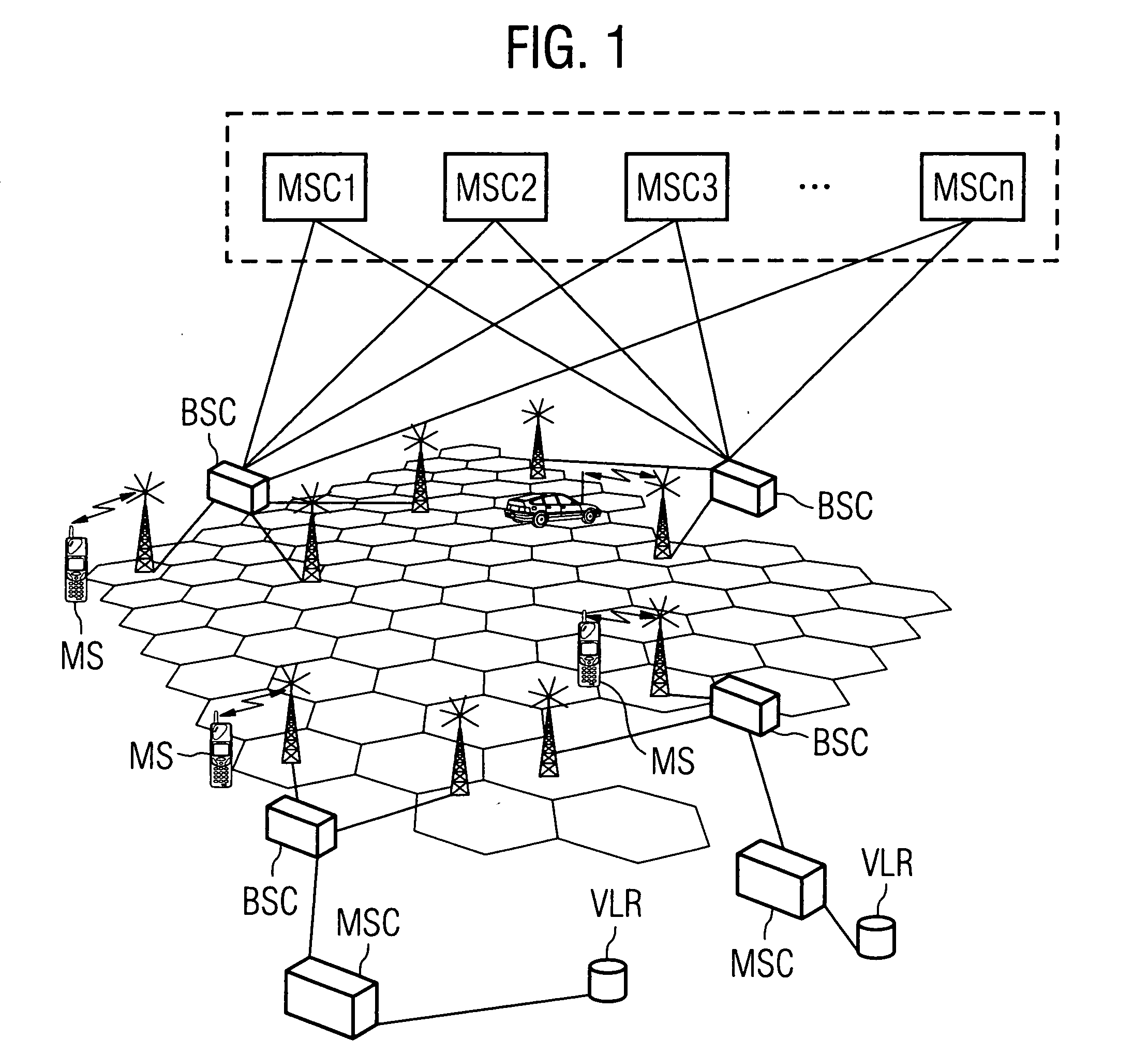
[0076]FIG. 1 shows an overview on a pooling concept according to the present invention supporting relay functionality during mobile station terminating signaling. This pooling concept allows for the extension of service capabilities in an existing mobile cellular communication network.

[0077] Components similar or identical to those previously discussed with respect to FIG. 11 have been denoted using the same reference numerals and the repeated explanation thereof is omitted. Further, in the following those elements upstream the...


PUM


Abstract

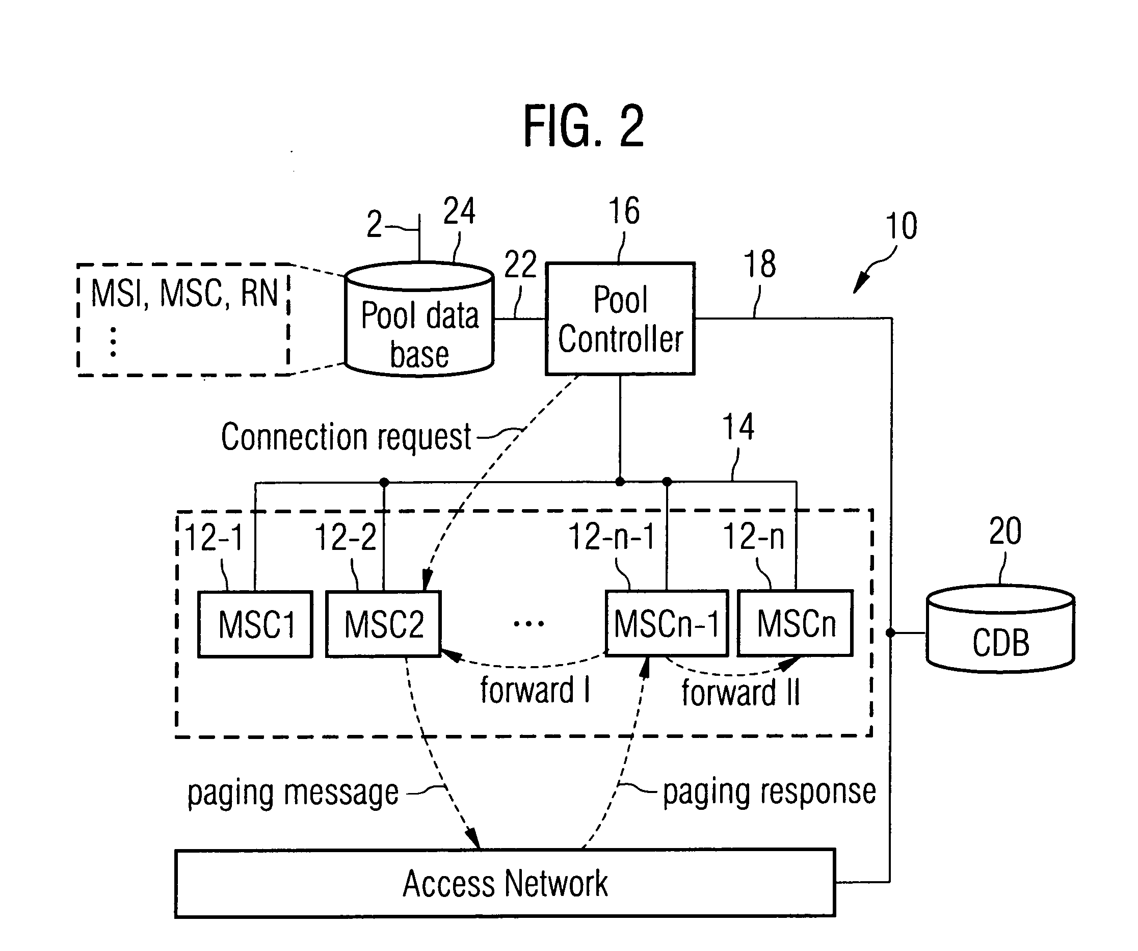
To achieve an efficient and flexible routing of signaling messages between a core network and an access network in a mobile communication cellular network, it is proposed to provide a pool of mobile switching apparatuses between the core network and the access network. Each mobile switching apparatus in the pool (10) comprises a signaling unit (32) adapted to issue a paging message to the access network for connection establishment to a mobile terminal. Further, according to the present invention it is proposed to provide each mobile switching apparatus in the pool (10) with a relay unit (28) adapted to receive a paging response from the access network. Further, the relay unit (28) is adapted to determine a mobile switching apparatus in the pool (10) of mobile switching apparatuses handling the paging response.

Description

FIELD OF INVENTION [0001] The present invention relates to a mobile switching apparatus for use in a pool of mobile switching apparatuses provided for a mobile cellular communication network, a pool of mobile switching apparatuses, a router apparatus for operation between at least one access network control apparatus and a pool of mobile switching apparatuses and related methods. BACKGROUND OF INVENTION [0002] Basic subsystems for the architecture of mobile cellular communication systems are a core network and a radio access network. [0003] As shown in FIG. 11, the core network comprises a gateway switching center GMSC, a mobile switching center MSC, further a home location register HLR, and a visitor location register VLR. The gateway switching center GMSC is connected to a plurality of mobile switching centers MSC and each mobile switching center MSC is connected to a visitor location register VLR. Different visitor location registers VLR are connected to the home location registe...

Claims


Application Information

Patent Timeline
Patent Type & Authority Applications(United States)
IPC IPC(8): H04L12/28H04L12/56H04W28/08H04W68/00H04W76/04H04W92/02H04W92/14
CPCH04W28/08H04W68/00H04W92/14H04W92/02H04W88/14H04W28/088
Inventor TURINA, KLAUSKUSTER, JOSEPHUSPAPADIMITRIOU, DIMITRIS
Owner TELEFON AB LM ERICSSON (PUBL)
Learn More