AI technical title is built by PatSnap AI team. It summarizes the technical point description of the patent document.
a self-shielding, syringe technology, applied in the field of syringes, can solve the problems of limiting the relative sliding relationship between the shield and the body, and achieve the effects of reducing manufacturing costs, preventing substantial lateral movement of the syringe within the body during use, and facilitating mass production
Inactive Publication Date: 2005-03-10
SAFETY SYRINGES
View PDF52 Cites 43 Cited by
Summary
Abstract
Description
Claims
Application Information
AI Technical Summary
This helps you quickly interpret patents by identifying the three key elements:
Problems solved by technology
Method used
Benefits of technology
Benefits of technology
[0014] Generally, after the cartridge or pre-filled syringe in the guard has been used to deliver its medication, the shield is moved distally until it reaches the guarded position. In the guarded position, the stop tabs on the body abut the proximal edges of the windows, preventing further distal movement. As the shield is moved, the detents on the shield leave the proximal detent pockets, preferably because of sloping edges on the proximal detent pockets, and slide along the body until they enter a set of distal detent pockets when the shield reaches the guarded position. The distal detent pockets may have blunt or oblique proximal edges, which prevent the shield from being returned proximally, and thereby substantially lock the shield in the guarded position for disposal. Preferably, the proximal edges of the detent pockets are inclined at an angle corresponding substantially to the proximal edges of the detents to maximize bearing surface engagement therebetween.
[0031] It is also an object to provide an improved syringe guard that affords improved protection for a cartridge or pre-filled syringe encapsulated therein but still allows effective monitoring of the medication being dispensed.
Problems solved by technology
One or more windows, preferably the same windows used for viewing the cartridge, also cooperate with a stop tab or tabs molded on the body, thereby limiting the relative sliding relationship of the shield and the body.
Method used
Image
Click on the blue label to locate the original text in one second.
Reading with bidirectional positioning of images and text.
Examples
Embodiment Construction
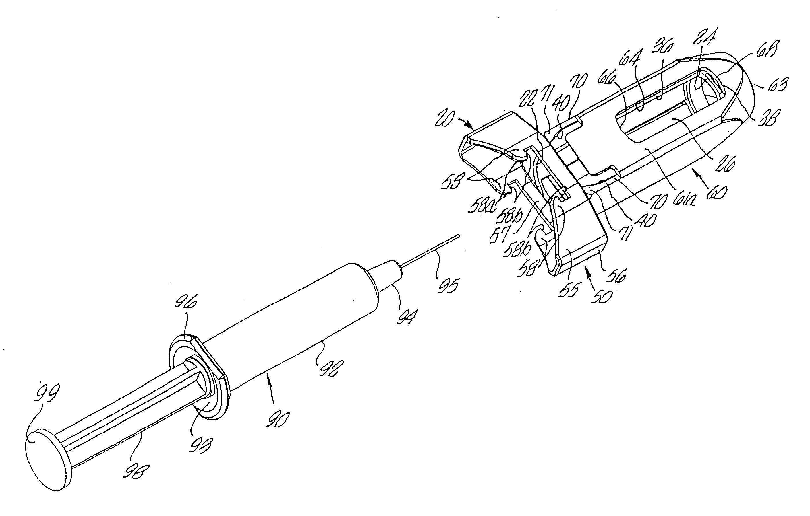
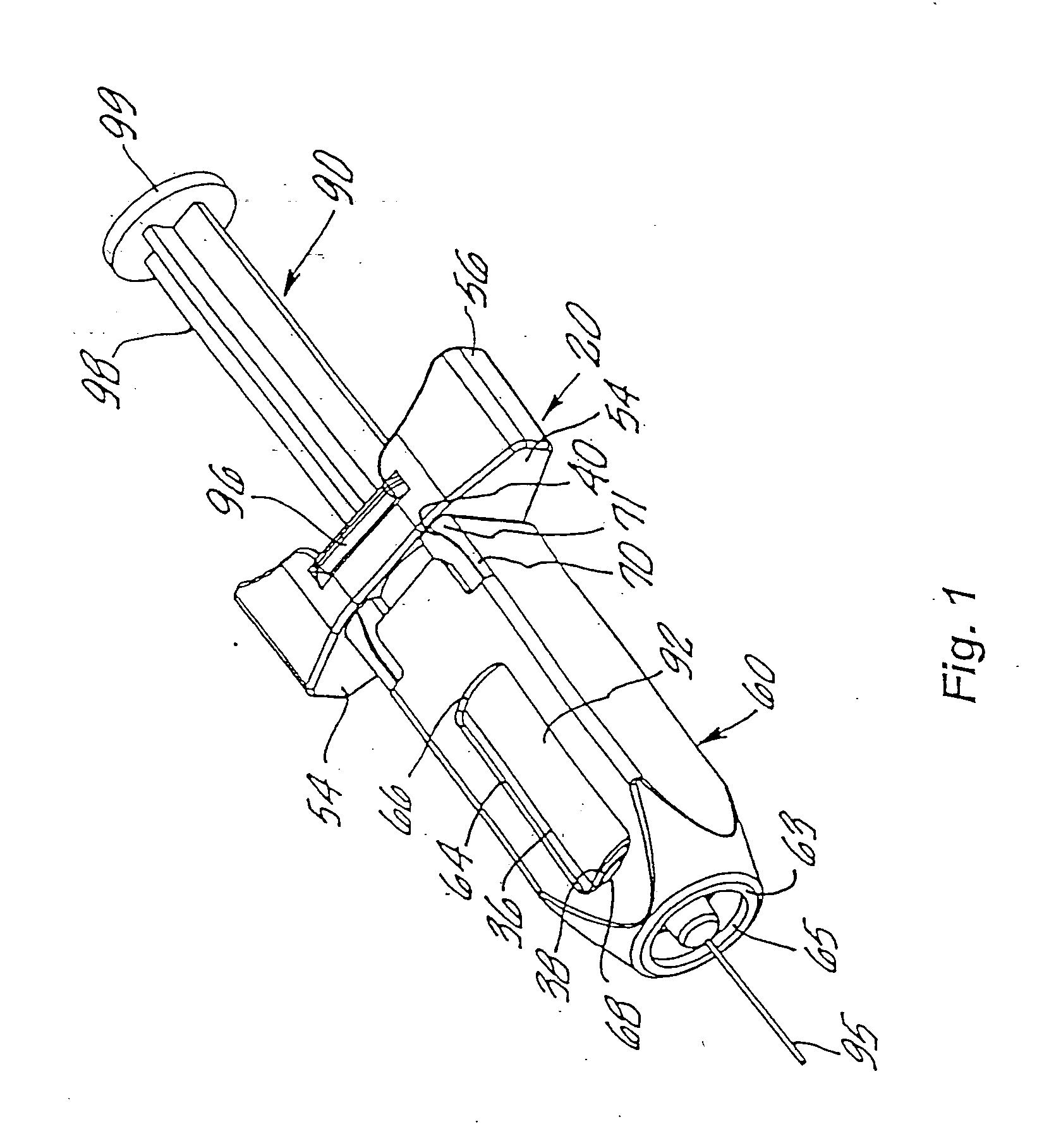
[0073] Turning to the drawings, FIG. 1 shows a first preferred embodiment of the present invention, namely a syringe guard 10 for holding a pre-filled unit dose syringe 90. Generally, the guard 10 comprises two-parts, namely a housing or body 20 for receiving and holding the pre-filled syringe 90, and a protective case or shield 60 slidably attached to the body 20. Both the body 20 and the shield 60 are generally molded from plastic, such as polypropylene, K-Resin®) (synthetic resinous polymers of butadiene and styrene), or polycarbonate, and are preferably clear and substantially colorless to facilitate observation of the pre-filled syringe received therein. Alternatively they may be translucent or opaque, and may be colored, such as a latex color, or a flesh tone, such as off-white, brown, or black.
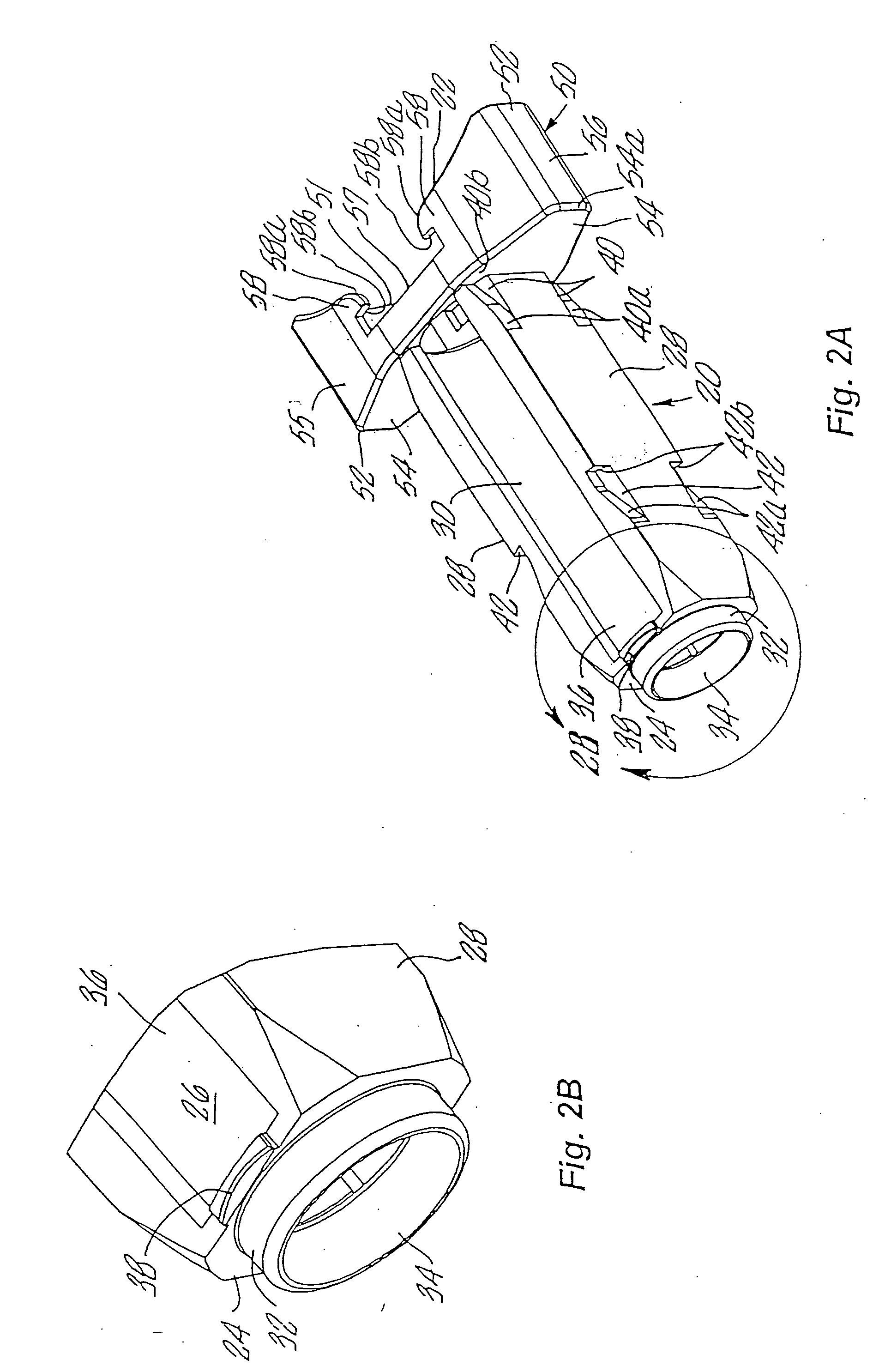
[0074] Turning to FIGS. 2A, 2B and 2C, the body 20 is an elongate member, preferably having a substantially rectangular cross-section, comprising two side rails 28, an open proximal en...
PUM
Abstract
An improved guard for a medical cartridge, such as a unit dose pre-filled glass syringe, comprising a body for receiving the cartridge, and a shield slidably attached to the body which are pre-assembled and ready to receive a cartridge therein. The body has a mechanism on a proximal end thereof which holds the cartridge therein. The body and shield have cooperating detents and detent pockets which allow the shield to be directed distally, from an unguarded position in which the needle on the cartridge is uncovered for delivery of medication, to a guarded position in which the needle is permanently covered for disposal. The body may also include a substantially rectangular-shaped finger grip on its proximal end for receiving a similarly shaped proximal flange on the cartridge, whereby the cartridge is received in a predetermined orientation.
Description
CROSS REFERENCE TO RELATED APPLICATIONS [0001] This application is a continuation of application Ser. No. 10 / 023,587, filed Dec. 17, 2001, which is a continuation of co-pending application Ser. No. 09 / 634,689, now U.S. Pat. No. 6,344,032, filed Aug. 8, 2000, which is a continuation of application Ser. No. 08 / 942,938 filed on Oct. 2, 1997, now U.S. Pat. No. 6,159,184, which is a continuation-in-part of application Ser. No. 08 / 814,199, filed Mar. 10, 1997, now U.S. Pat. No. 6,171,283, all of which are fully incorporated herein by reference.FIELD OF THE INVENTION [0002] The present invention relates generally to syringes, and more particularly to an improved syringe guard for a unit dose cartridge or pre-filled syringe and including a shield for covering the needle thereof after medication is dispensed from the syringe. BACKGROUND OF THE INVENTION [0003] Medication is often dispensed using a unit dose medical cartridge, such as an ampule, vial or syringe, and a syringe holder, injector...
Claims
Application Information
Patent Timeline
Application Date:The date an application was filed.
Publication Date:The date a patent or application was officially published.
First Publication Date:The earliest publication date of a patent with the same application number.
Issue Date:Publication date of the patent grant document.
PCT Entry Date:The Entry date of PCT National Phase.
Estimated Expiry Date:The statutory expiry date of a patent right according to the Patent Law, and it is the longest term of protection that the patent right can achieve without the termination of the patent right due to other reasons(Term extension factor has been taken into account ).
Invalid Date:Actual expiry date is based on effective date or publication date of legal transaction data of invalid patent.
Patent Type & AuthorityApplications(United States)

