Integral type air conditioner and front panel thereof

a technology of integral type and air conditioner, which is applied in the direction of heating types, lighting and heating apparatus, and domestic cooling devices, etc. it can solve the problems of type air conditioner, foreign particles such as dust, etc., and accumulate on a plurality, so as to enhance the appearance of integral type air conditioner, enhance the efficiency of air conditioner, and enhance the appearance of the front side of the air conditioner

a technology of integral type and air conditioner, which is applied in the direction of heating types, lighting and heating apparatus, and domestic cooling devices, etc. it can solve the problems of type air conditioner, foreign particles such as dust, etc., and accumulate on a plurality, so as to enhance the appearance of integral type air conditioner, enhance the efficiency of air conditioner, and enhance the appearance of the front side of the air conditioner

US20050056037A1Inactive Publication Date: 2005-03-17LG ELECTRONICS INC

Image

  • Integral type air conditioner and front panel thereof
  • Integral type air conditioner and front panel thereof
  • Integral type air conditioner and front panel thereof

Examples


Embodiment Construction

[0048] Reference will now be made in detail to the preferred embodiments of the present invention, examples of which are illustrated in the accompanying drawings.

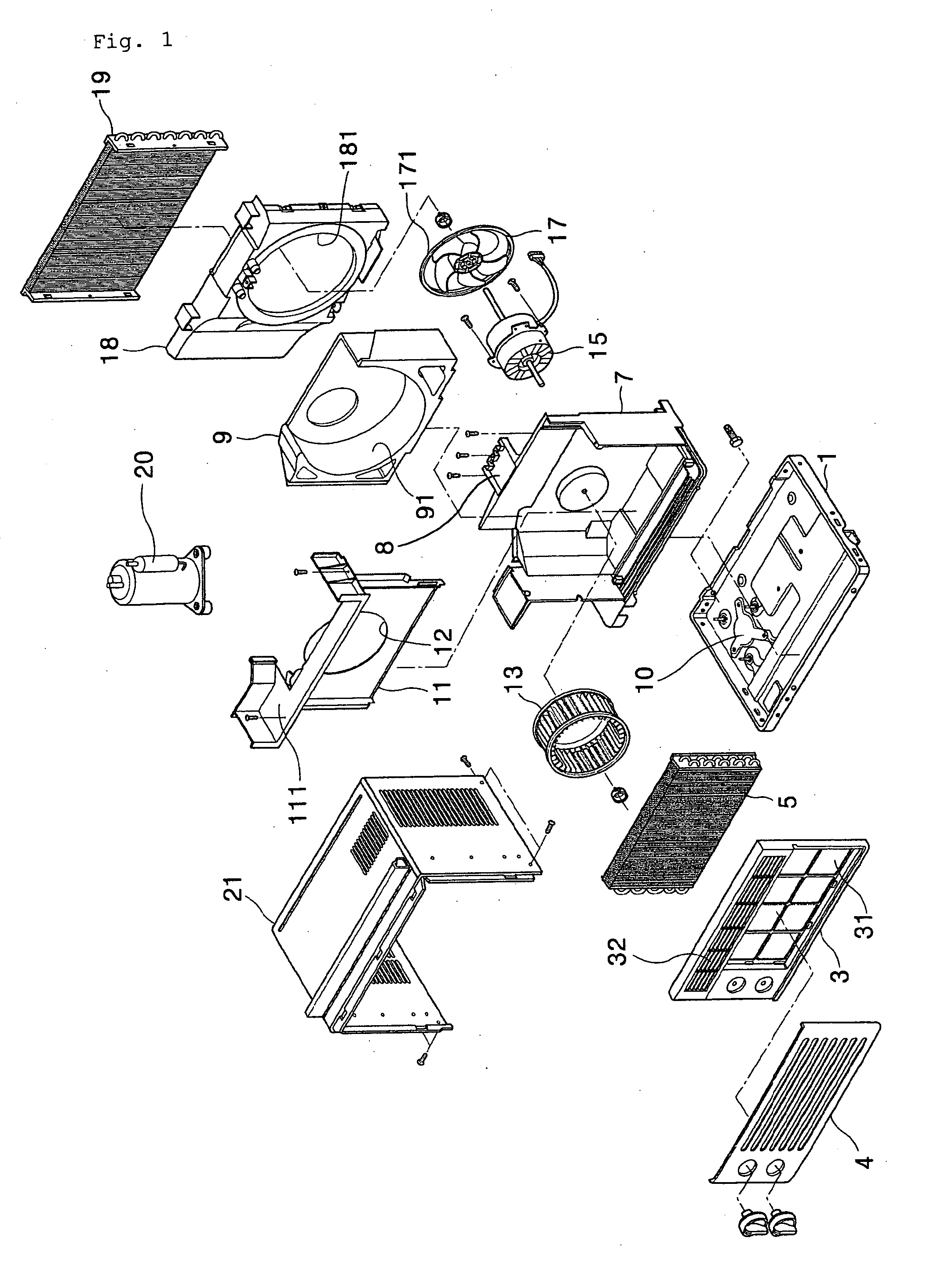
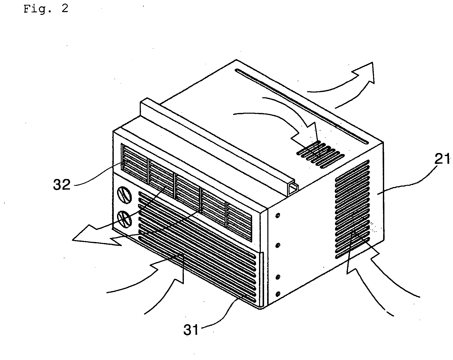
[0049]FIG. 3 is a partial cutaway perspective view of an integral type air conditioner according to a preferred embodiment of the present invention, and FIG. 4 is an exploded perspective view of an integral type air conditioner according to the present invention. As shown, an integral type air conditioner includes a base panel 100 constituting the bottom of the air conditioner, a cabinet 700 constituting the appearance of the air conditioner and in which various parts constituting a heat exchange cycle are received, an indoor unit part received in the indoor side of the cabinet 700 and which warm air is taken in through and cool air is exhausted, and an outdoor unit part received in the outdoor unit part of the cabinet 700 so as to cool working fluid.

[0050] Hereinafter, the construction of the indoor unit part will be des...


PUM


Abstract

A front panel for an integral type air conditioner is provided. The front panel includes a side intake hole formed at a side portion thereof such that air from a space to be air conditioned is taken in there through. The front panel also has a discharge hole through which the intake air is discharged.

Description

[0001] This application claims the benefit of Korean Patent Application No. 2003-63980, filed on Sep. 16, 2003 and Korean Patent Application No. 2003-68590, filed on Oct. 2, 2003 which is hereby incorporated by reference for all purposes as if fully set forth herein. BACKGROUND OF THE INVENTION [0002] 1. Field of the Invention [0003] The present invention relates to a front panel of an air conditioner, and more particularly, to an inlet / outlet portion of a front panel of an integral type air conditioner, where the inlet / outlet portion of the front panel intakes and discharges air. [0004] 2. Description of the Related Art [0005] In a general integral type air conditioner, an indoor unit part and an outdoor unit part are constructed as a single body. This obviates the need to employ a long hose. It also facilitates, among other things, installation and transportation. Further, the indoor unit part is disposed indoors to cool air, and the outdoor unit part is disposed outdoors to cool ...

Claims


Application Information

Patent Timeline
17 Mar 2005
Publication
US20050056037A1
IPC
F24F1/00; F24F1/02; F24F13/20
CPC
F24F1/0011; F24F13/20; F24F1/027
Inventors
PARK, HAE YONG; KIM, MYUNG SOO