Composite belt structure and a method of manufacturing

a belt structure and composite technology, applied in the field of pneumatic tires, can solve the problems of high degree of flexure in the crown area of pneumatic tires for high-speed applications, affecting the performance of pneumatic tires, cutting off and scattering of belts and treads,

Active Publication Date: 2005-03-17
THE GOODYEAR TIRE & RUBBER CO
View PDF21 Cites 18 Cited by
  • Summary
  • Abstract
  • Description
  • Claims
  • Application Information

AI Technical Summary

Benefits of technology

[0021]“Chafers” refer to narrow strips of material placed around the outside of the bead t

Problems solved by technology

Pneumatic tires for high speed applications experience a high degree of flexure in the crown area of the tire as the tire enters and leaves the contact patch.
This problem is particularly exacerbated on aircraft tires wherein the tires can reach speed of over 200 mph at takeoff and landing.
In U.S. Pat. No. 5,427,167, Jun W

Method used


Image

  • Composite belt structure and a method of manufacturing
  • Composite belt structure and a method of manufacturing
  • Composite belt structure and a method of manufacturing

Examples


Embodiment Construction

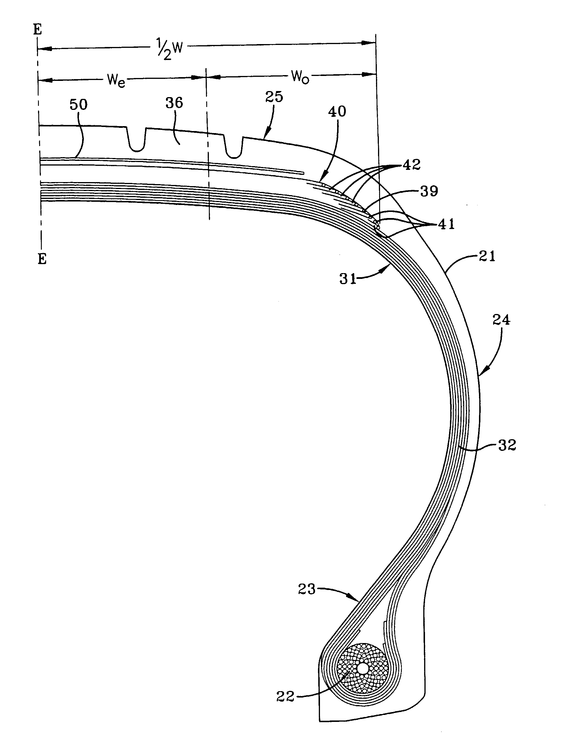
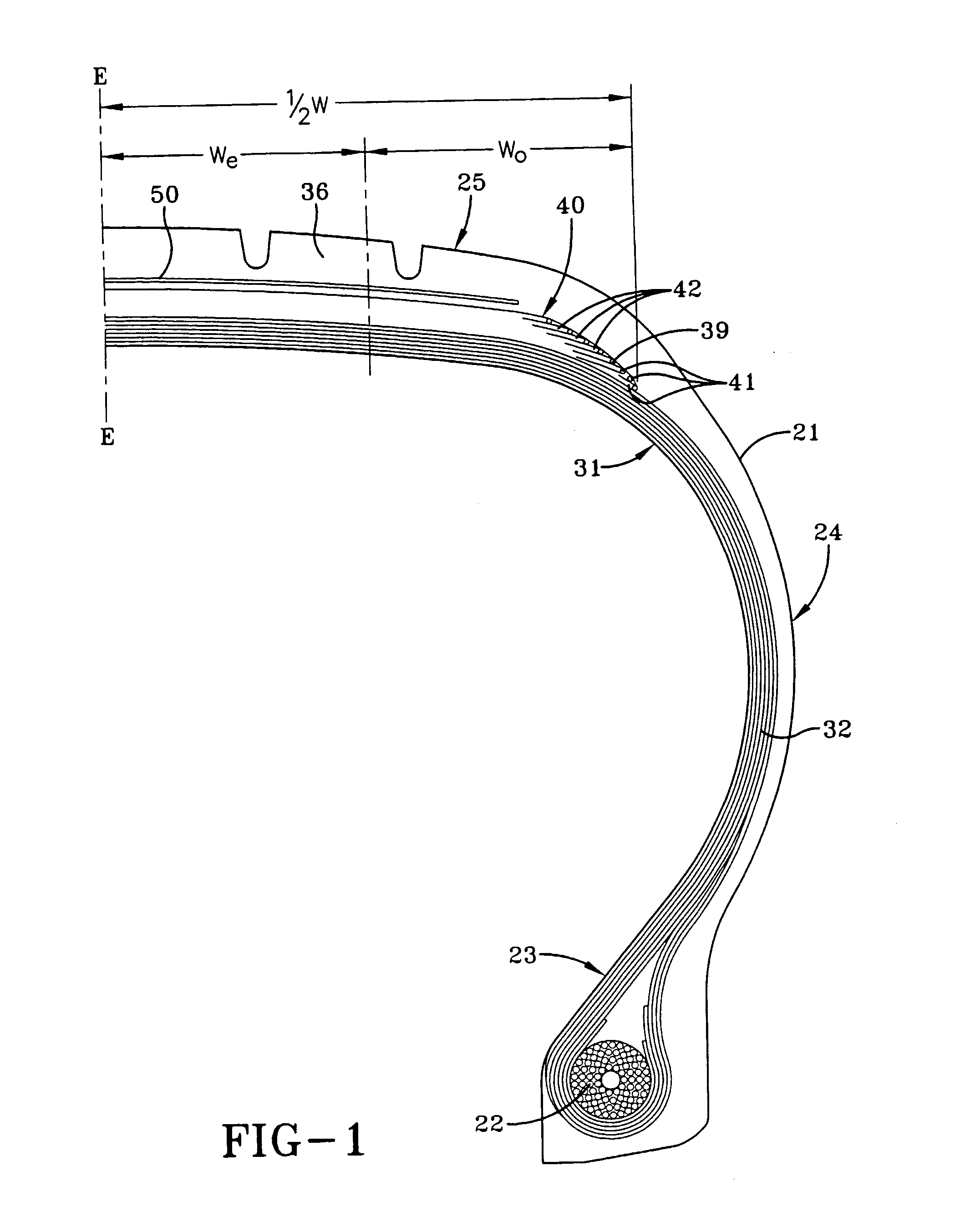
[0047] In FIGS. 1 and 2, numeral 21 is a radial tire of the preferred embodiment of the invention, as shown, to be mounted onto an airplane, which comprises a pair of bead portions 23 each containing a bead core 22 embedded therein, a sidewall portion 24 extending substantially outward from each of the bead portions 23 in the radial direction of the tire, and a tread portion 25 of substantially cylindrical shape extending between radially outer ends of these sidewall portions 24. Furthermore, the tire 21 is reinforced with a carcass 31 toroidially extending from one of the bead portions 23 to the other bead portion 23. The carcass 31 is comprised of at least two carcass plies 32, e.g. six carcass plies 32 in the illustrated embodiment. Among these carcass plies 32, four inner plies are wound around the bead core 22 from inside of the tire toward outside thereof to form turnup portions, while two outer plies are extended downward to the bead core 22 along the outside of the turnup po...


PUM


Abstract

The method of forming a composite belt structure 40 for a tire 21 is disclosed. The method discloses the steps of applying a multicord 46 reinforced strip 43 having a strip width SW onto a rotating crowned building drum, the strips 43 being wound in a zigzag configuration to form at least two zigzag layers 41 wherein the crowned drum has non-overlapping portions of the strips 43 placed in a central portion and extending in alternation to a pair of shoulder portions having portions of the strips 43 overlapping, the central portion having a maximum diameter Do and the shoulder portions have a minimum diameter Di, the adjacent strips 43 being placed apart from 0 to 2 mm in the central portion and the strips 43 are increasingly overlapping in each shoulder portion as the strips 43 extend from the central portion toward lateral ends of the belt structure 40 to form belt layers 39, 40. 42 of a composite belt structure 40 having the cords per inch in the shoulder portion as measured axially inwardly from the axially inner edge of the strip adjacent the lateral ends of the narrowest radially outer belt layer 42 radially inwardly greater than the cords per inch in the central portion as measured centered on the centerplane of the belt structure. The resultant method produces a pneumatic tire 21 having a carcass 31 and a belt reinforcing structure 40, the belt reinforcing structure 40 having a composite belt structure of cord reinforced layers 39,40,41 including at least two radially outer zigzag belt layers 42.

Description

FIELD OF THE INVENTION [0001] This invention relates to pneumatic tires having a carcass and a belt reinforcing structure, more particularly to high speed heavy load radial ply tires such as those used on aircraft. BACKGROUND OF THE INVENTION [0002] Pneumatic tires for high speed applications experience a high degree of flexure in the crown area of the tire as the tire enters and leaves the contact patch. This problem is particularly exacerbated on aircraft tires wherein the tires can reach speed of over 200 mph at takeoff and landing. [0003] When a tire spins at very high speeds the crown area tends to grow in dimension due to the high angular accelerations and velocity tending to pull the tread area radially outwardly. Counteracting these forces is the load of the vehicle which is only supported in the small area of the tire known as the contact patch. [0004] In U.S. Pat. No. 5,427,167, Jun Watanabe of Bridgestone Corporation suggested that the use of a large number of belt plies ...

Claims


Application Information

Patent Timeline
IPC IPC(8): B29D30/30B60C9/18B29D30/70B60C9/20B60C9/22B60C9/26B60C19/00
CPCB29D30/3035B29D30/70B60C9/2204Y10T152/10855B60C2200/02Y10T152/10783B60C9/263
Inventor UEYOKO, KIYOSHISLIVKA, JOHN JOSEPHVILLANUEVA, ROEL DOMINGOBOEHLEFELD, ROBERT JOHN
Owner THE GOODYEAR TIRE & RUBBER CO
Why Eureka
Try Eureka