Sensor position adjusting device for a coin dispenser

Inactive Publication Date: 2005-03-17
ASAHI SEIKO CO LTD
View PDF5 Cites 14 Cited by
  • Summary
  • Abstract
  • Description
  • Claims
  • Application Information

AI Technical Summary

Benefits of technology

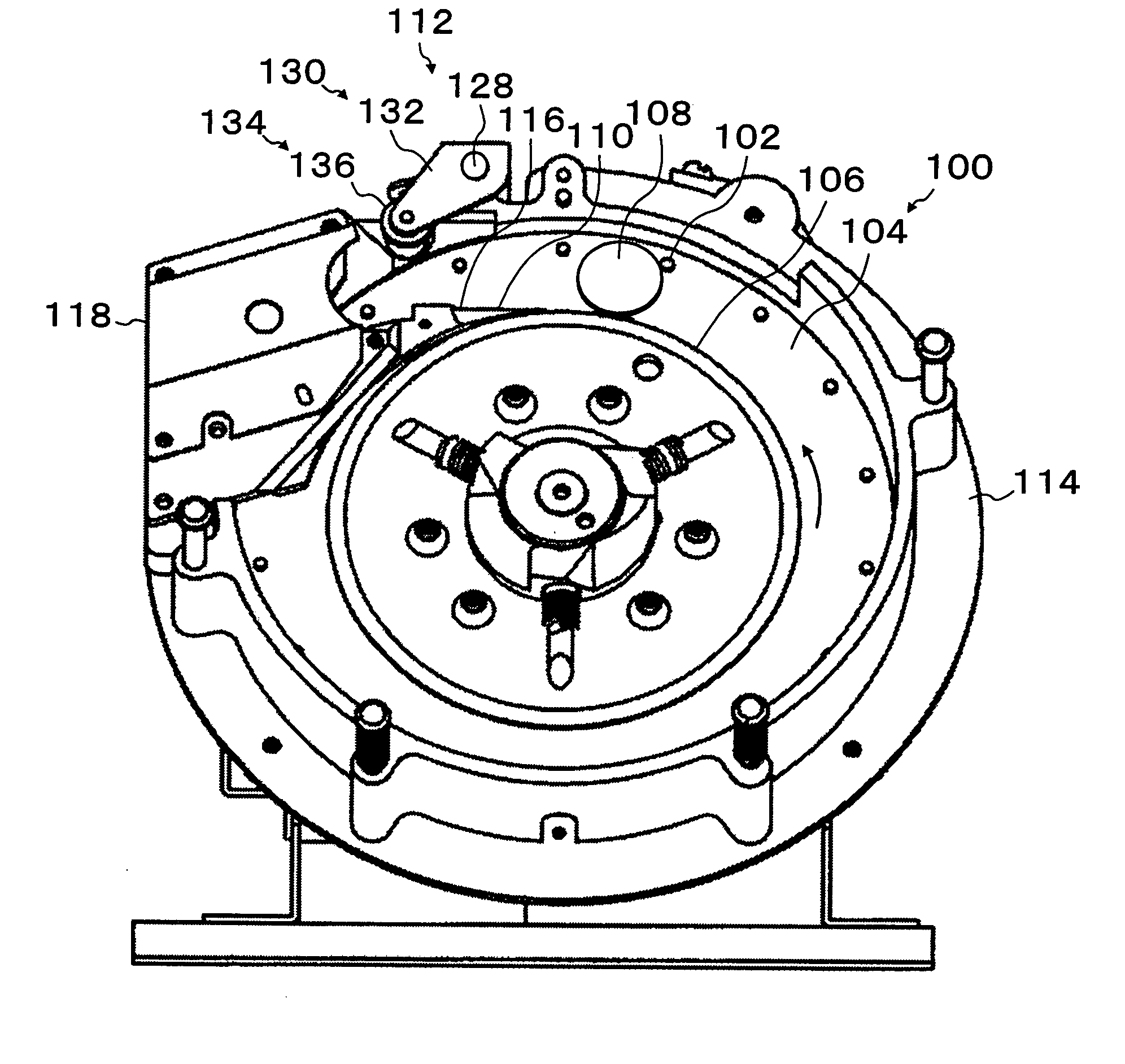
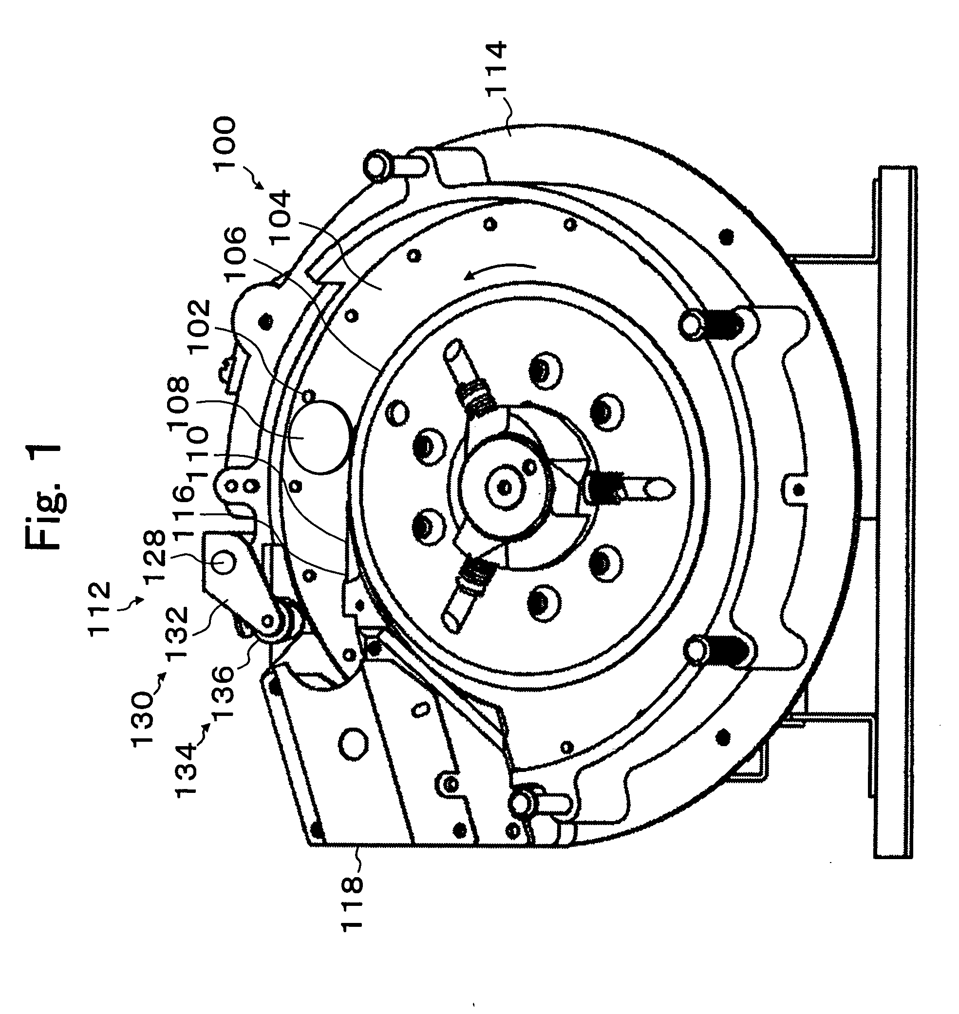
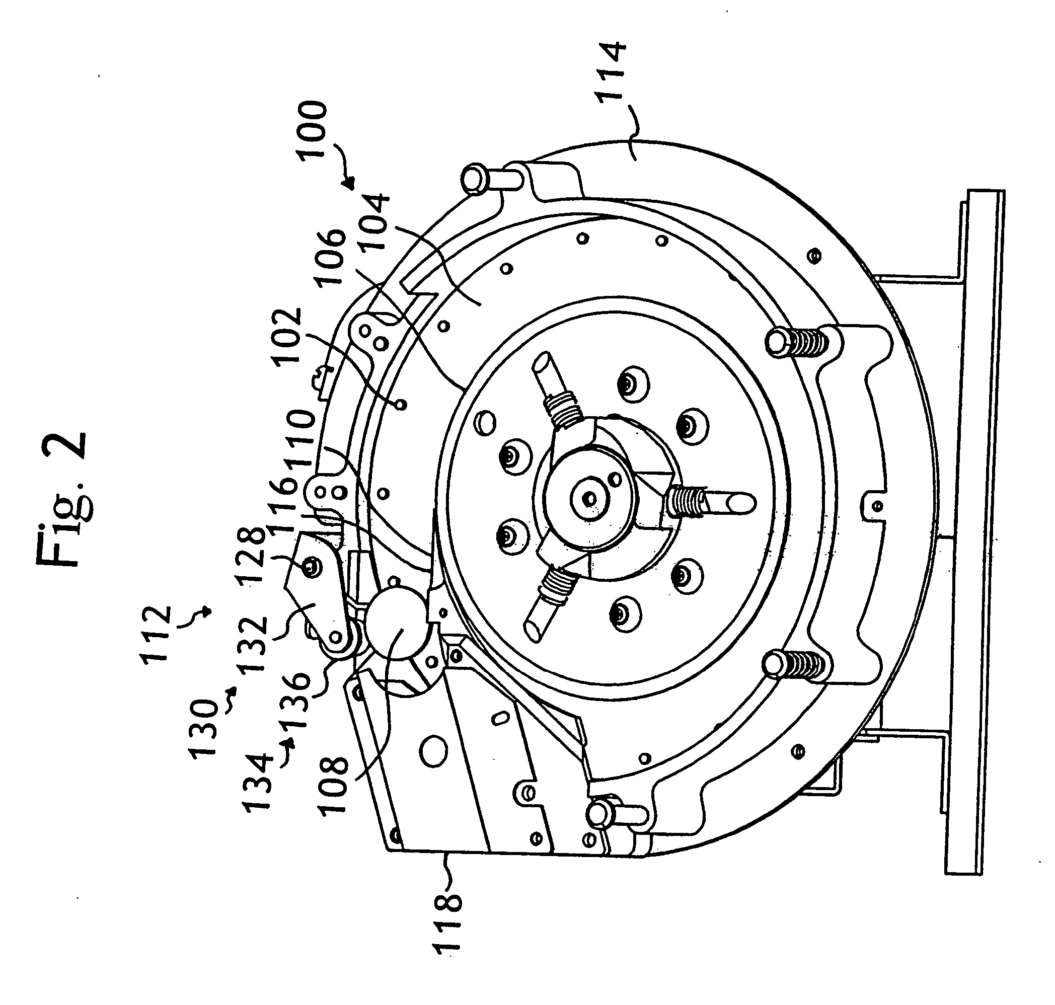
[0006] The present invention addresses the limitations of the prior art by providing a sensor position adjusting device including a screw unit for accurately adjusting the position of the sensor unit relative to a driven member moved by a dispensed coin.
[0007] The sensor position adjusting device includes a rotatable coin selecting disc member for selectively dispensing coins, a driven member that is moved by the dispensed coins, a sensor unit for detecting the movement of the driven member, and a screw unit for accurately adjusting the position of the sensor unit relative to the driven member.
[0010] Once the proper position of the sensor unit is determined, a fixing unit can secure the movable base plate against movement relative to the fixed base plate so the sensor unit can maintain the determined position. The fixing unit applies force in a direction that is perpendicular to the plane of adjustment so that by fixing the position of the movable base plate, the adjustment position of the sensor is not altered.

Problems solved by technology

However, the position of the sensor relative to the lever arm cannot be easily and precisely adjusted, and often can move out of the desired position as the sensor is secured.
The position of the sensor can be adjusted relative to the lever by adjusting a screw, but the adjustment is performed by hand and can be imprecise.
This imprecision may require multiple attempts to properly position the sensor relative to the lever.

Method used


Image

  • Sensor position adjusting device for a coin dispenser
  • Sensor position adjusting device for a coin dispenser
  • Sensor position adjusting device for a coin dispenser

Examples


Embodiment Construction

[0018] Reference will now be made in detail to the preferred embodiments of the invention, examples of which are illustrated in the accompanying drawings. While the invention will be described in conjunction with the preferred embodiments, it will be understood that they are not intended to limit the invention to these embodiments. On the contrary, the intention is intended to cover alternatives, modifications and equivalents, which may be included within the spirit and scope of the invention as defined by the appended claims.

[0019] Furthermore, in the following detailed description of the present invention, numerous specific details are set forth in order to provide a thorough understanding of the present invention. However, it will be obvious to one of ordinary skill in the art that the present invention may be practiced without these specific details. In other instances, well known methods, procedures, components, and circuits have not been described in detail as not to unnecess...


PUM


Abstract

A device for accurately adjusting the position of a sensor unit relative to a driving member. The driving member is moved by a coin dispensed by a coin dispenser. The sensor unit is mounted on a movable base plate that is positioned on a fixed base plate attached to the coin dispenser. The relative position of the sensor unit to the driving member is adjusted by a screw unit that can adjust the position of the movable base plate relative to the fixed base plate. A fixing unit secures the movable base plate from moving relative to the fixed base plate once the desired sensor unit position is selected using the screw unit.

Description

FIELD OF THE INVENTION [0001] The present invention is related to sensor position adjusting device and more particularly to a sensor position adjusting device for a coin dispenser that can be adjusted easily and precisely. DESCRIPTION OF RELATED ART [0002] A coin dispenser having a dispensing disk having a plurality of pins on the dispensing disk for dispensing coins one at a time, is known. The dispensed coins can move a lever arm in proximity to a sensor for detecting dispensed coins. However, the position of the sensor relative to the lever arm cannot be easily and precisely adjusted, and often can move out of the desired position as the sensor is secured. [0003] U.S. Pat. No. 4,437,478 granted to Abe discloses a device where the dispensed coins or tokens contact a roller that moves an actuating arm to interact with a sensor. The actuating arm moves between a pair of spaced-apart sensor coils to define a slot for receiving one end of the actuating arm. [0004] Japanese Patent No. ...

Claims


Application Information

Patent Timeline
IPC IPC(8): G07D5/00G07D9/00
CPCG07D9/008G07D5/00
Inventor SEAGLE, DONALD LEEKOPALA, STANLEY JOHN
Owner ASAHI SEIKO CO LTD
Why Eureka
Try Eureka