Compact material marking system and method

Inactive Publication Date: 2005-03-17
NOVANTA CORP
View PDF4 Cites 9 Cited by
  • Summary
  • Abstract
  • Description
  • Claims
  • Application Information

AI Technical Summary

Benefits of technology

[0006] The present invention resides in a compact material marking system. Embodiments include a system having a laser configured to emit a laser beam and a surface configured to receive a material to be struck by the laser beam. An enclosure is coupled to the laser. The enclosure is shaped and positioned with respect to the surface t

Problems solved by technology

Unfortunately, these conventional laser-based marking systems are designed with certain degrees of safety, ope

Method used


Image

  • Compact material marking system and method
  • Compact material marking system and method
  • Compact material marking system and method

Examples


Example

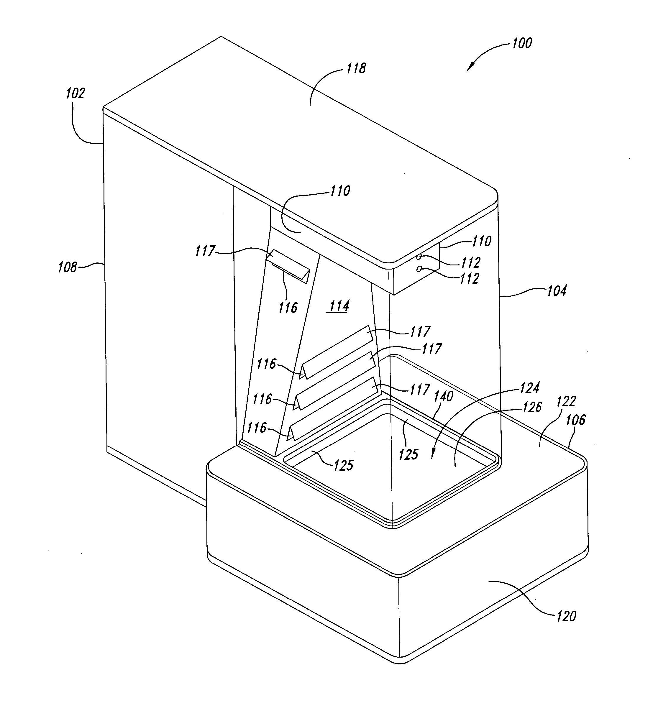
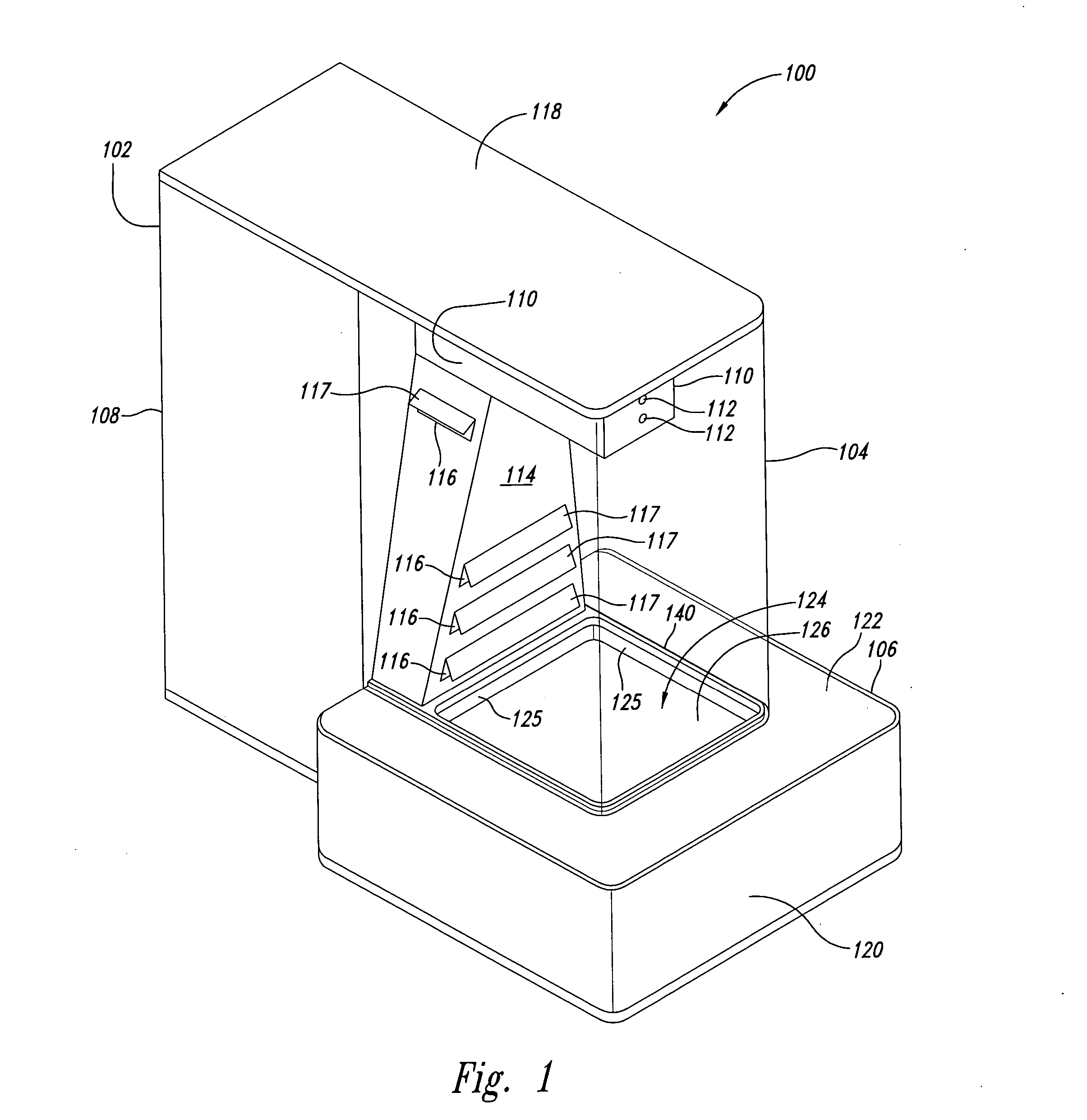
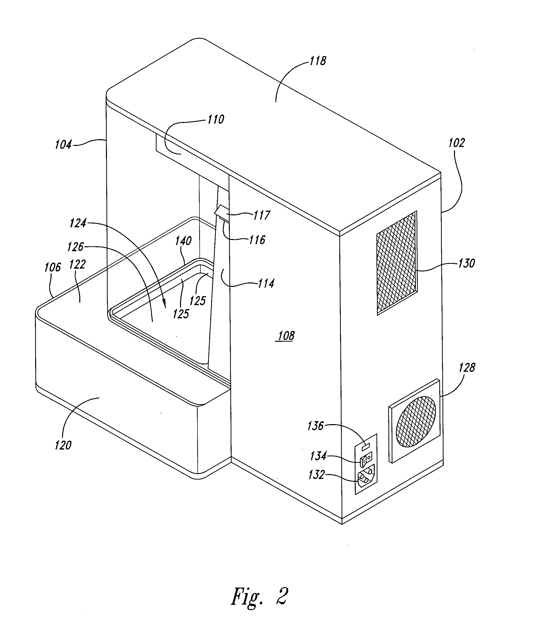
[0030] As will be discussed in greater detail below, a compact material marking system disclosed herein can be used to mark materials in a variety of operational settings by relatively unskilled users. Both safety and environmental quality issues associated with operation are addressed and thereby allows operation by persons such as customers in locations such as stores. Consequently, the existing scope of possible application and implementation of laser-based marking can be greatly expanded.

[0031] An implementation of the compact material marking system according to the present invention is shown in FIG. 1 as a marking system 100 having a housing 102, an enclosure 104 (typically transparent but opaque to laser wavelengths used) and a material cassette 106. The housing 102 includes an equipment container 108 to house devices for generating a laser beam and handling noxious fumes generated as described further below. The housing 102 also includes a laser beam container 110 that hous...


PUM

PropertyMeasurementUnit
Wavelengthaaaaaaaaaa
Interactionaaaaaaaaaa

Abstract

A compact material marking system and method uses a laser to mark materials such as fabrics in environments such as stores with safety and ease of use being addressed. The system includes a housing containing the laser, gas filters, and other equipment such as fans. Material to be marked is placed into a cassette box having an opening exposing the material. The cassette is engaged with an enclosure that is coupled to the housing to allow the laser beam from the laser to enter the enclosure and to strike the material found in the engaged cassette. Fumes caused by interaction of the laser beam with the material are contained by the enclosure and drawn away to be filtered. Sensors are employed so that the laser can be activated only when the cassette is fully engaged with the enclosure.

Description

BACKGROUND OF THE INVENTION [0001] 1. Field of the Invention [0002] The present invention is directed generally to systems for marking materials and, more particularly, to laser systems for marking materials. [0003] 2. Description of the Related Art [0004] Laser-based marking systems and methods for marking materials such as fabrics are conventionally known. In certain areas of the fashion industry, these conventional systems are widely used by manufacturing companies to mark clothing such as denim jackets and jeans. [0005] Unfortunately, these conventional laser-based marking systems are designed with certain degrees of safety, operational complexity, and size in mind such that their use is confined to restricted areas by trained operators. BRIEF SUMMARY OF THE INVENTION [0006] The present invention resides in a compact material marking system. Embodiments include a system having a laser configured to emit a laser beam and a surface configured to receive a material to be struck by ...

Claims


Application Information

Patent Timeline
IPC IPC(8): B41J2/435D06M10/00
CPCB23K26/036B23K26/12B23K26/123B23K26/127D06H1/00D06M10/005B23K2201/007B23K26/0342B23K2101/007
Inventor CLARKE, DAVIDWHEELER, JOHN R.WROBEL, PHILIP A.SYMBOL, JEFFREY P.WARREN, JEFFREY M.SILTA, RAYMOND L.HOUGARDY, PETER J.
Owner NOVANTA CORP
Why Eureka
Try Eureka