Monitoring of receiver type usage in a printing machine

a technology of printing machine and receiver, applied in the field of digital printing, can solve the problems of printing documents at very high resolution and precision, affecting the mechanical components of the printing machine, and requiring extremely tight mechanical tolerances

Inactive Publication Date: 2005-03-17
REYNOLDS TIMOTHY W
View PDF7 Cites 11 Cited by
  • Summary
  • Abstract
  • Description
  • Claims
  • Application Information

AI Technical Summary

Benefits of technology

[0010] It is therefore an object of this invention to provide a printing machine and method of operating the same in which the effects of different receiver sheet types on machine reliability and consumable use can be monitored.

Problems solved by technology

Modern electrophotographic printing machines operate at extremely high volumes, yet are required to print documents at very high resolutions and precision, necessitating extremely tight mechanical tolerances.
It is known that the printing of each receiver sheet will effect some amount of wear on various mechanical components of the printing machine, such as rollers that handle the receiver sheets at the transfer station (at which toner is transferred from a photoconductor to a receiver sheet) and at the fuser station (at which toner is fused to the receiver sheet).
Several components in the image loop are also subject to wear as each sheet is printed.
In addition to wear effects, each receiver sheet that is printed also contributes to contamination of the printing machine.
This contamination includes dust and particles from the receiver sheets themselves, as well as toner residue, release oils, and other materials involved in the printing of each sheet.
In addition to wear and contamination, it is known that the rate at which the printing machine consumes materials such as toner, release oil, and the like, varies with the type of receiver sheets printed.
Indeed, the price charged by a service provider for maintenance of a printing machine is often based on a metered count of images printed, with higher meter counts resulting in a higher service contract price over time.
This variation in receiver sheet usage will result in varying wear of printing machine components, in varying contamination, and in varying usage of consumables, for the reasons mentioned above.
This can result in economic loss for the service provider, or for the printing machine owner in the case of a user-serviced installation.

Method used


Image

  • Monitoring of receiver type usage in a printing machine
  • Monitoring of receiver type usage in a printing machine
  • Monitoring of receiver type usage in a printing machine

Examples


Embodiment Construction

[0019] The present invention will be described in connection with its preferred embodiment, namely as implemented into an electrographic printing machine, as it is believed that this invention will be especially beneficial in such an application. However, it is also contemplated that this invention may also provide similar important benefits in other implementations than an electrographic printing machine as described. Accordingly, it is to be understood that the following description is provided by way of example only, and is not intended to limit the true scope of this invention as claimed.

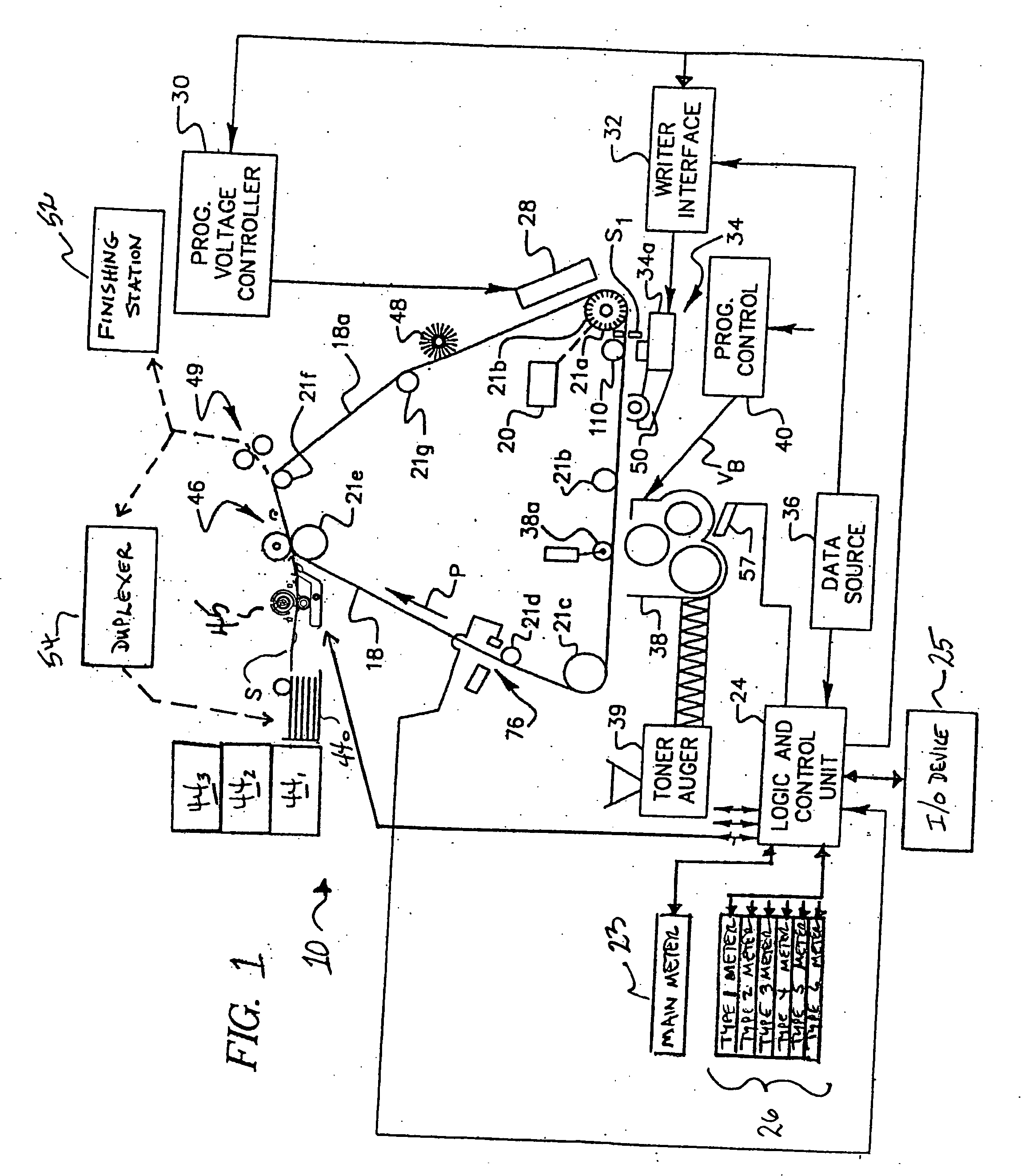
[0020] Referring now to FIG. 1, printing machine 10 according to the preferred embodiment of the invention will now be described. In electrographic printing machine 10 of FIG. 1, photoconductor 18, which is a moving recording member such as a photoconductive film belt, is entrained about a plurality of rollers or other supports 21a through 21g, one or more of which is driven by a motor to advan...


PUM


Abstract

An electrographic printing machine (10) including multiple print counters (23; 26) is disclosed. The printing machine (10) is capable of printing images on various receiver sheet types, including transparencies, label stock, and of course paper of various composition, finish, size, and color. A main print counter (23) keeps a count of each sheet printed by the printing machine (10), regardless of receiver sheet type. Receiver sheet type counters (26) are each associated with a receiver sheet type, and maintain counts of sheets printed by receiver sheet type. The contents of type counters 26 can be used in the calculation of printing charges, maintenance intervals, and the like, considering that machine wear, contamination, and use of consumables varies for various receiver sheet types.

Description

CROSS-REFERENCE TO RELATED APPLICATIONS [0001] This application claims the priority date of U.S. Provisional Application Ser. No. 60 / 503,656 filed Sep. 17, 2003 entitled “MONITORING OF RECEIVER TYPE USAGE IN A PRINTING MACHINE”.STATEMENT REGARDING FEDERALLY SPONSORED RESEARCH OR DEVELOPMENT [0002] Not applicable. BACKGROUND OF THE INVENTION [0003] This invention is in the field of digital printing, and is more specifically directed to the management of high volume electrophotographic printing machines. [0004] Electrographic printing has become a prevalent technology in the modern computer-driven printing of text and images, on a wide variety of hard copy media. This technology is also referred to as electrographic marking, electrostatographic printing or marking, and electrophotographic printing or marking. Conventional electrographic printers are well suited for high resolution and high speed printing, with resolutions of 600 dpi (dots per inch) and higher becoming available even a...

Claims


Application Information

Patent Timeline
Patent Type & Authority Applications(United States)
IPC IPC(8): G03G21/02
CPCG03G21/02
Inventor REYNOLDS, TIMOTHY W.
Owner REYNOLDS TIMOTHY W
Why Eureka
Try Eureka