USB function apparatus

a function apparatus and usb technology, applied in the field of usb function apparatuses, can solve the problems of inability to operate the camera and the inability of the usb function apparatus to perform any operation

Active Publication Date: 2005-03-17
FUJIFILM CORP
View PDF5 Cites 46 Cited by
  • Summary
  • Abstract
  • Description
  • Claims
  • Application Information

AI Technical Summary

Benefits of technology

[0010] With this configuration, when the host apparatus does not start communications in spite of the current USB descriptor transmitted in response to the descriptor request (also referred to as the “descriptor read request”) from the host apparatus, the control device of the USB function apparatus switches the USB descriptor to generate a bus reset. It is thus possible to ensure communications between the USB host apparatus and the USB function apparatus.
[0014] This configuration makes it possible to set whether or not to automatically switch the USB descriptor. A fixed descriptor is transmitted if the USB descriptor is not set to be automatically switched.

Problems solved by technology

Then, the camera cannot be operated even when it transmits the USB descriptor representing the still image class function to the personal computer.
Consequently, the USB function apparatus cannot perform any operation.

Method used


Image

  • USB function apparatus
  • USB function apparatus
  • USB function apparatus

Examples


first embodiment

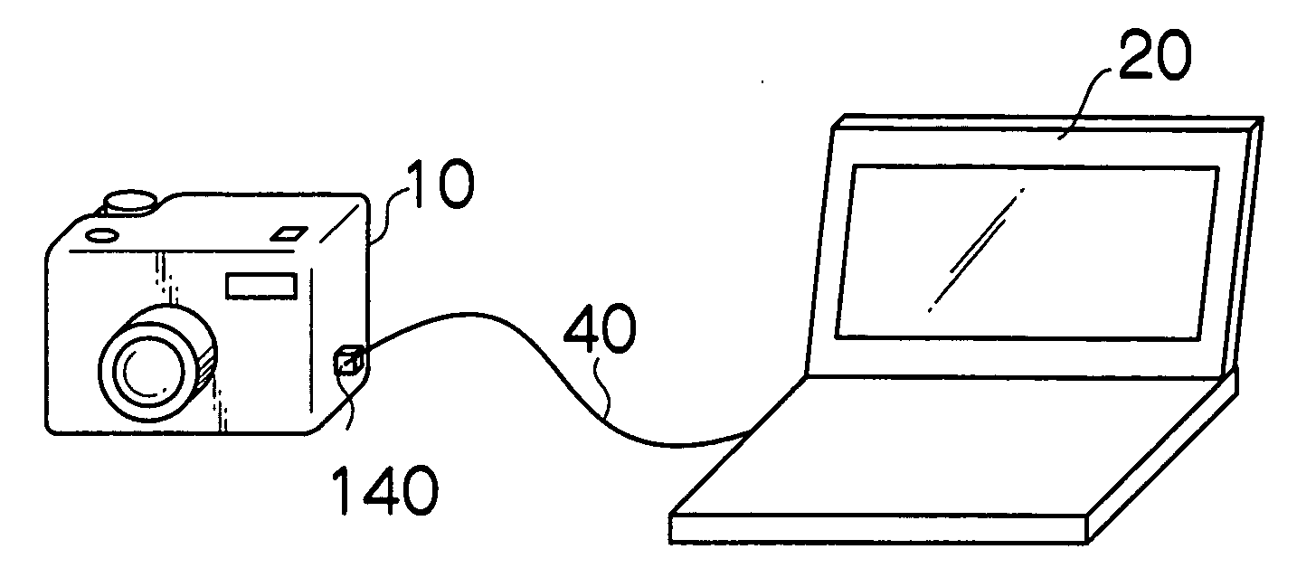
[0030] The application of the present invention to a camera will be described below. The camera is connected to a USB host such as a personal computer (hereinafter simply referred to as a “PC”) or a printer via a USB (Universal Serial Bus) to operate as a USB function.

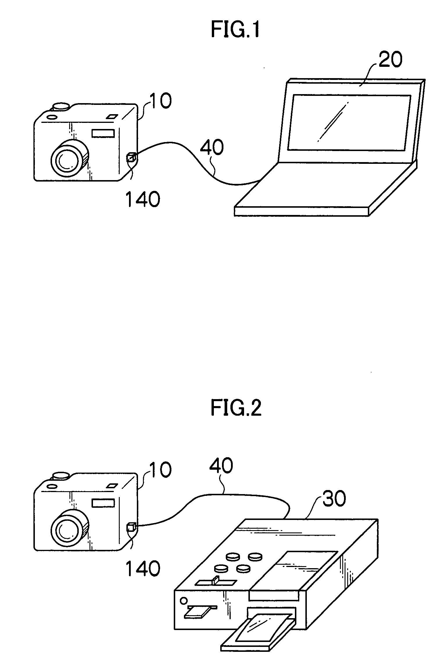
[0031]FIG. 1 shows how a camera 10 is connected to a PC 20 via a USB cable 40. In FIG. 1, the PC 20 functions as a USB host, and the camera 10 operates as a USB function of a mass storage class (MSC). Specifically, the camera 10 functions as an external storage device for the PC 20, operating as a USB host. If the PC 20 operates as a USB host and the camera 10 operates as a USB function for a PC camera, the camera 10 consecutively transfers images being photographed to the PC 20 as motion pictures.

[0032]FIG. 2 shows how the camera 10 is connected to a printer 30 via the USB cable 40. In FIG. 2, the printer 30 operates as a USB host and the camera 10 operates as a USB function of a still image class (SIC). Communicati...

second embodiment

[0070] In a second embodiment, unlike the first embodiment, the CPU 101 allows the timer 105 to start clocking when the USB function driver 142 detects a descriptor read request from the USB host. Upon detecting a timeout, the CPU 101 switches the current USB descriptor set in the USB function driver 142.

[0071] With reference to the flow chart in FIG. 10, description will be given of operations of the camera 10 according to the present embodiment.

[0072] In the description below, the three USB descriptors 601, 602, and 603 are pre-registered in the USB descriptor list 600 as shown in FIG. 6, and in the setup screen 700 in FIG. 7, the “AUTO” mode is preset.

[0073] In FIG. 10, first, the current function number n is initialized to “1” (S202). Then, on the basis of the descriptor list 600 in FIG. 6, the descriptor 601 (the mass storage class), having the function number “1”, is set in the USB function driver 142 as shown in FIG. 8A (S204). Then, the VBUS detecting section 141 monitors...


PUM


Abstract

The present invention provides a USB function apparatus which supports a plurality of USB descriptors and which is connected to a host apparatus via a USB to operate as a USB function, the USB function apparatus comprising a descriptor switching device which switches one of the plurality of USB descriptors to be transmitted to the host apparatus, a bus reset generating device which generates a bus reset to initialize communications with the host apparatus, and a control device which causes the descriptor switching device to switch the USB descriptor and causes the bus reset generating device to generate a bus reset when a descriptor request from the host apparatus is responded with a current USB description but if the host apparatus does not start communications in accordance with the USB descriptor.

Description

BACKGROUND OF THE INVENTION [0001] 1. Field of the Invention [0002] The present invention relates to a USB function apparatus, and in particular, to a USB function apparatus which supports a plurality of USB descriptors. [0003] 2. Description of the Related Art [0004] A USB function apparatus has been proposed which supports a plurality of USB descriptors corresponding to a plurality of functions. With this apparatus, if a user selects one of the plurality of functions, the USB descriptor corresponding to the function selected by the user is transmitted to a USB host apparatus (see Japanese Patent Application Publication No. 2001-202325). For example, if a camera (USB function apparatus) has a mass storage class function (which allows the camera to be treated as an external storage device) and a still image class function (that allows the camera to transfer each still image), when the user selects the mass storage class function on the camera, the USB descriptor representing the mas...

Claims


Application Information

Patent Timeline
Patent Type & Authority Applications(United States)
IPC IPC(8): G06F13/12G06F13/36G06F13/38G06F13/42
CPCG06F3/1423G09G5/006G06F2213/0042G06F13/4282
Inventor TANAKA, HIROSHI
Owner FUJIFILM CORP
Why Eureka
Try Eureka