
Template system for locating and cutting wall or ceiling openings

a technology for locating and cutting ceiling openings, applied in the direction of cables, instruments, constructions, etc., can solve the problems of affecting the alignment and attachment of the wall plate covering the outlet, affecting the stability, and being less able to support and secure the gang box, so as to achieve quick and efficient positioning of cutouts

Inactive Publication Date: 2005-03-24
BOYS MARK A
View PDF16 Cites 4 Cited by
  • Summary
  • Abstract
  • Description
  • Claims
  • Application Information

AI Technical Summary

Benefits of technology

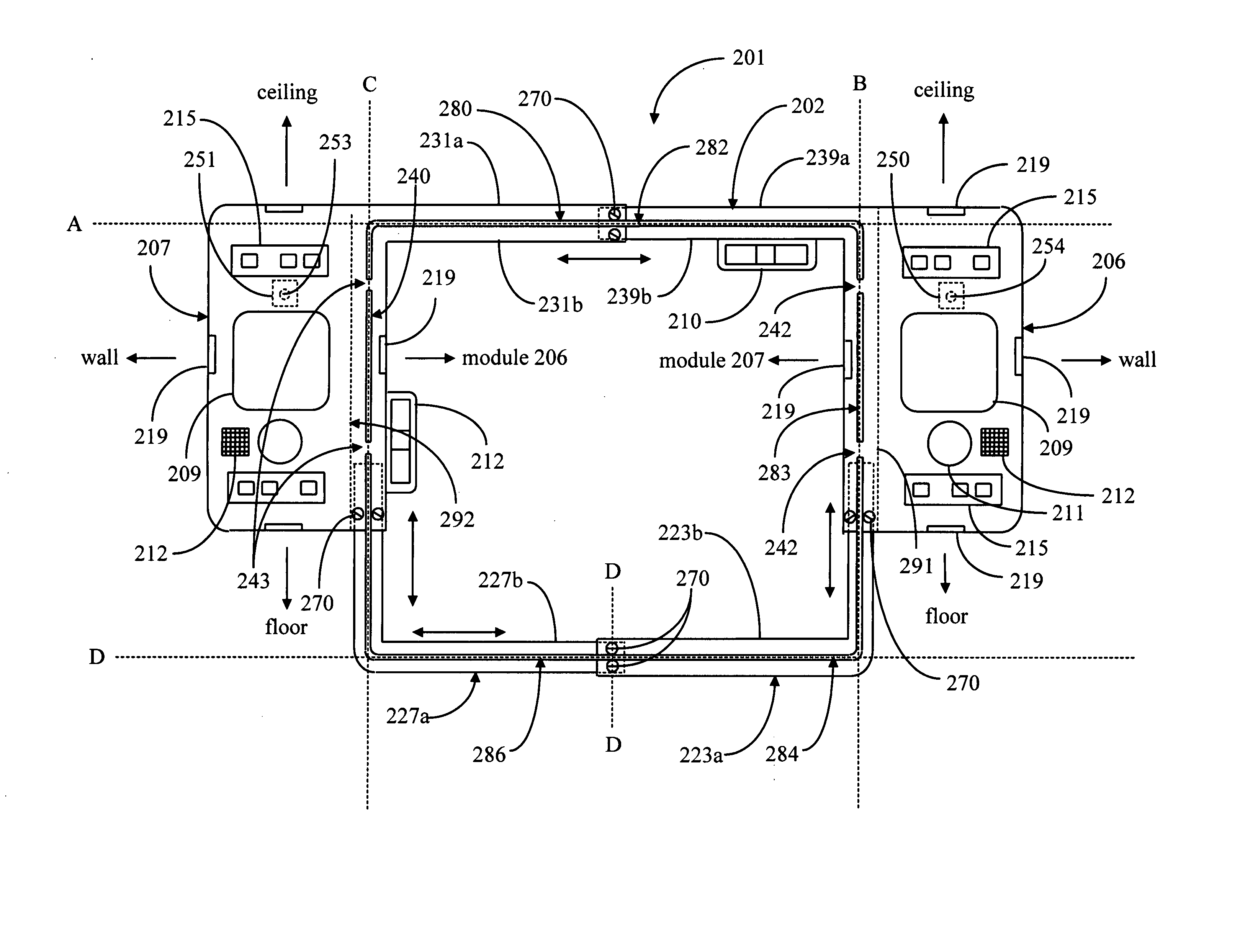
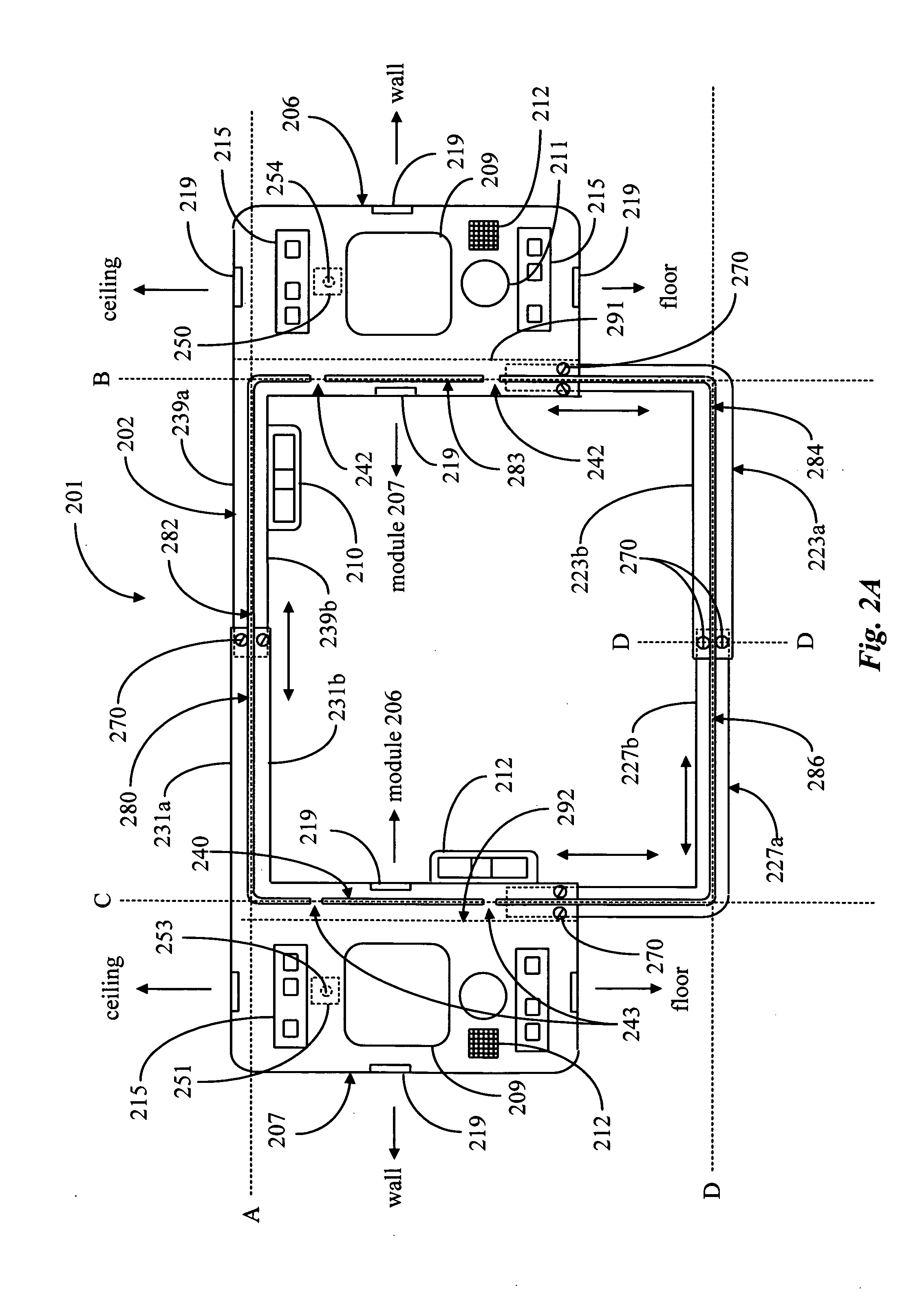
[0023] In embodiments of the present invention taught in enabling detail below, for the first time a template system is provided that very quickly and efficiently locates cutouts in drywall, and guides a cutting tool in making the cutouts.

Problems solved by technology

Stability is further compromised in a drywall-mounted gang box application when the drywall, for whenever reason be it moisture damage, or deterioration over time, becomes softer and less able to support and secure the gang box.
If such a gang box opening is not perfectly located and aligned, upon securing the gang box to the stud, damage to the drywall may occur due to misalignment between the gang box and the opening, and may also adversely affect the alignment and attachment of the wall plate covering the outlet.
Such methods for locating and scribing the opening, utilizing an electronic stud finder and carpenter's level or hand-held template, for instance, easily lend themselves to errors in scribing or cutting the opening, because of the manual nature of the actions.
When utilizing a hand-held paper gang box opening template, accurate marking around the periphery of the paper template is often difficult and prone to error, and hand-held leveling templates utilizing such as spiral cutting tools, or roto-zip tools as they are often referred to as, are often difficult to manually hold stationary to drywall while cutting the opening with the cutting tool around the periphery of the template.
An inherent functional limitation in hand-held gang box opening templates is that the templates are typically available in sizes applicable to either a single-gang box opening, or a dual-gang opening, or in some instances, both.
Such a hand-held template provides no advantage, however, to one wishing to easily cut a square and level opening of a size different from what is required for a standard single or dual gang box, such as for a junction box for wiring of a local area network (LAN), for instance.
Slight variances in the dimensions of “old work” gang boxes may require openings having dimensions slightly different from standard, posing further problems to the user of a conventional hand-held gang box opening template.

Method used


Image

  • Template system for locating and cutting wall or ceiling openings
  • Template system for locating and cutting wall or ceiling openings
  • Template system for locating and cutting wall or ceiling openings

Examples


Embodiment Construction

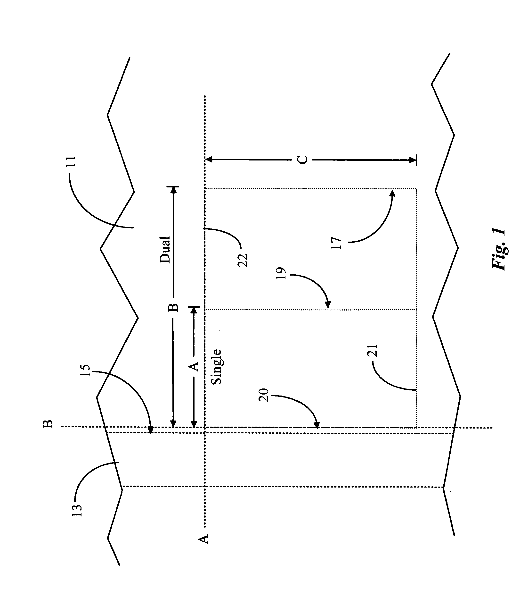
[0036]FIG. 1 illustrates an outline for an opening to be cut into a section of drywall, for both a single and a dual gang box opening, located adjacent to, and aligned with a vertical framing stud within a wall, to which a gang box is to be mounted. Drywall 11 covers stud 13 as is typical in the construction of a wall. Typically the outline of a rectangular cutout for a gang box is marked or scribed upon the outer surface of drywall 11, in a preferred position for installing either a single or dual gang box to stud 13. In order for proper alignment of the newly installed gang box, the left vertical edge of the cutout outline, represented by line 20 in the illustration, is adjacent to, and aligned with the right vertical edge of stud 13, represented as surface 15. In the illustration an outline for the cutout required for a single-gang opening is represented by the rectangular shape formed by line 19 intersected by lines 21 and 22, the rectangular outline having a width of dimension ...


PUM


Abstract

A template system for guiding drywall cutouts has at least one control box incorporating a stud-finder, and a system of interconnecting extensions attached to the control box, the extensions forming a predetermined geometrical shape. The template system is characterized in that, with the template system positioned against a drywall, individual edges of the interconnecting extensions serve as guides for a cutting tool to cut out a portion of the drywall in the predetermined geometrical shape formed by the interconnecting extensions.

Description

FIELD OF THE INVENTION [0001] The present invention is related to commercial or residential electrical wiring and component installation, and pertains more particularly to a template system for locating and cutting gang openings for installing stud-mounted “old work” electrical gang boxes. The invention is further directed to a template system for easily locating and cutting other openings of various sizes in a wall, ceiling or other surface. BACKGROUND OF THE INVENTION [0002] Wiring and other components for electrical, networking or other such systems in a residential or commercial structure is installed utilizing either “new work” or “old work” installation techniques. The term “new work”, such as when used with reference to installing wiring and components in new home construction, refers to installation of the wiring and components wherein the wiring and components are routed through and installed within the framing of the structure prior to installation of the drywall wall / ceil...

Claims


Application Information

Patent Timeline
Patent Type & Authority Applications(United States)
IPC IPC(8): B25H1/00E04F21/00H02G1/00
CPCB25H1/0078E04F21/00H02G2200/30Y10S33/10H02G1/00
Inventor BOYS, MARK A.
Owner BOYS MARK A
Learn More