Vehicle seat weight sensor

a weight sensor and vehicle seat technology, applied in the direction of instruments, pedestrian/occupant safety arrangements, force/torque/work measurement apparatus, etc., can solve the problems of uniform weight reading, injuring the occupants, and inability to detect the weight of the front passenger seat, so as to achieve reliable and cost-effective effects

Inactive Publication Date: 2005-03-24
CTS CORP ELKHART
View PDF63 Cites 77 Cited by
  • Summary
  • Abstract
  • Description
  • Claims
  • Application Information

AI Technical Summary

Benefits of technology

[0008] It is a feature of the invention to provide a reliable and cost-effective vehicle seat weight sensor for detecting the weight of a seat occupant. The sensor uses strain sensitive resistors.
[0009] An additional feature of the invention is to provide a weight sensor for sensing the weight of an occupant in a vehicle seat. The seat has a seat pan and a seat member. The weight sensor includes a case mounted between the seat pan and the seat member. One or more strain gauge resistors are mounted in the case. The resistors generate an electrical signal in response to the case being stressed by the weight of the seat occupant. The electrical signal changes as a function of the weight of the occupant. A fastener passes through the seat member, the case, and the seat pan. The fastener secures the sensor between the seat pan and the seat member. The case is adapted to transfer to the strain gage resistor the weight of the occupant up to a first magnitude. The case prevents the strain gage from receiving weight beyond that of the first magnitude.

Problems solved by technology

In some situations, these safety devices can injure the occupants.
For example, an occupant in the front passenger seat may be injured by deployment of an airbag, if the occupant is a baby or child.
One problem encountered in measuring the weight of a seat occupant is that the weight reading needs to be uniform when the vehicle is moving.
The load cells of the prior art have suffered from giving false readings when subjected to side loads.
Prior art seat weight sensors have suffered from requiring an extensive redesign of the seat frame in order to be installed.

Method used


Image

  • Vehicle seat weight sensor
  • Vehicle seat weight sensor
  • Vehicle seat weight sensor

Examples


case 70

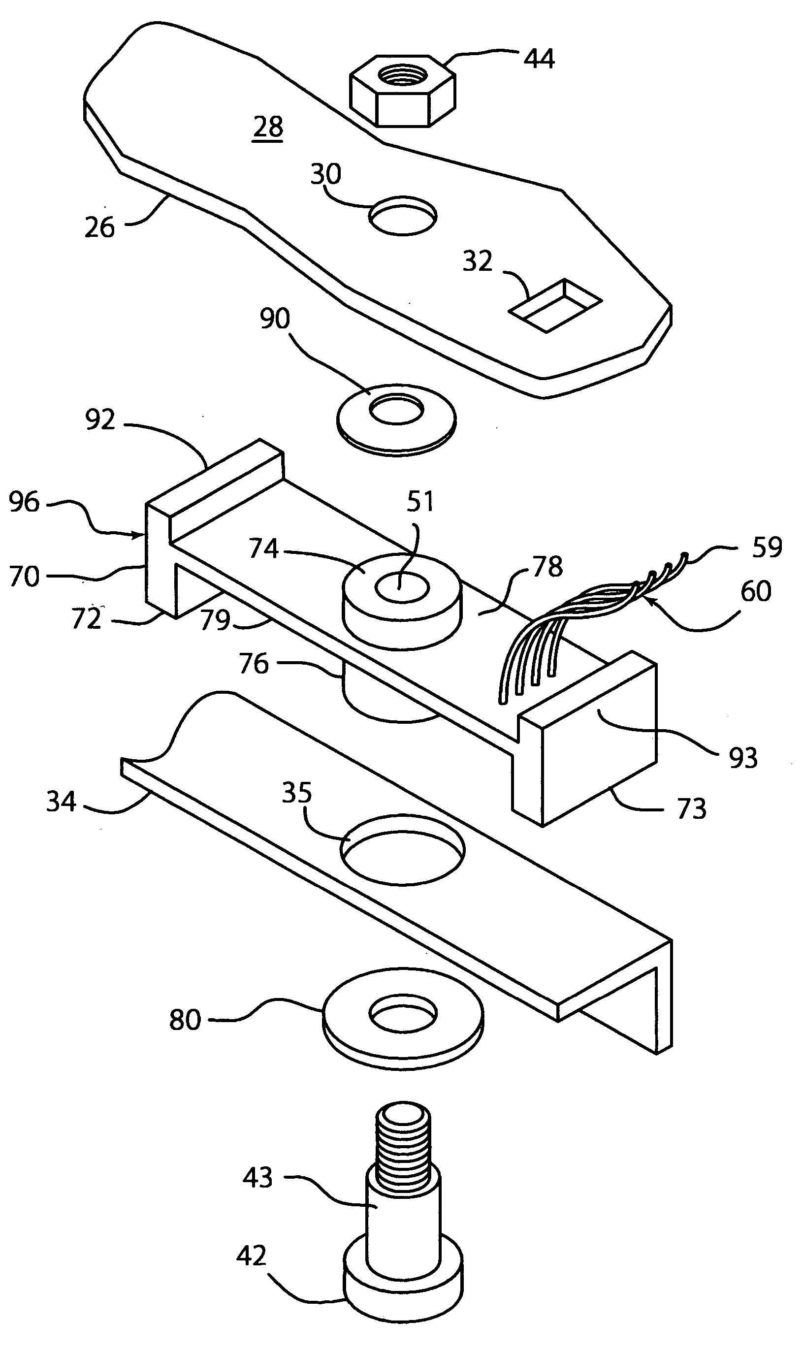
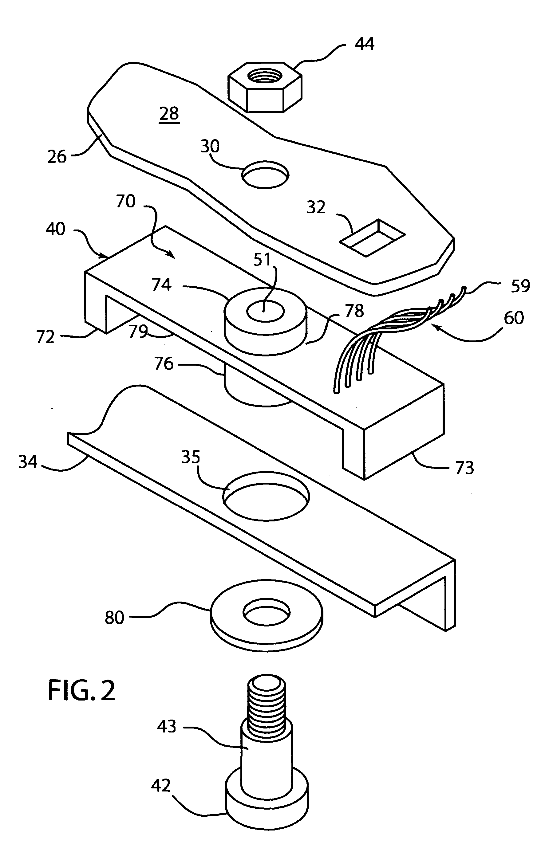
[0025] Case 70 is able to move slightly from side to side in hole 35, this allows side loads on assembly 20 that are not in the vertical axis to be absorbed by case 70 but not measured. In other words, case 70 decouples the strain gage resistors from side or off vertical axis loads. Sensor 40 therefore is somewhat insensitive to side loads which are undesirable to be measured. Loads in the vertical direction are representative of seat occupant weight and are measured by sensor 40.

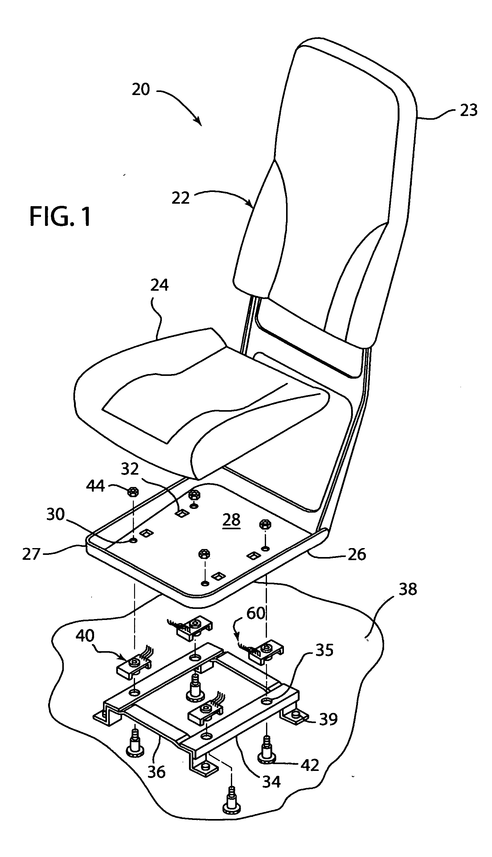
[0026] Referring to FIG. 3, lower boss 76 fits into hole 35. Upper boss 74 and lower boss 76 both surround shoulder 43. A gap 82 is formed between seat pan bottom 28 and top center portion 78. Similarly, another gap 84 is formed between rail 34 and bottom center portion 79. When an occupant sits on seat bottom 24, the seat occupants weight is transferred from seat bottom 24 to seat pan 26, through sensor 40, to seat member 34, then to carriage 36 and floor 38. The entire weight of the seat occupant is suppo...


PUM


Abstract

A seat weight sensor for detecting the weight of a seat occupant. The weight sensor has a case mounted between a seat pan and a seat member. One or more strain gauge resistors are mounted in the case. The resistors generate an electrical signal in response to the case being stressed by the weight of the seat occupant. The electrical signal changes as a function of the weight of the occupant. A fastener passes through the seat member, the case, and the seat pan. The fastener secures the sensor between the seat pan and the seat member. The case is adapted to transfer to the strain gage resistor the weight of the occupant up to pre-determined level. The case prevents the strain gage from receiving weight beyond that of the pre-determined level such that the sensor is not damaged by an excessive load. The case also allows the weight sensor to be insensitive to off-axis forces that might otherwise contribute to inaccurate weight readings.

Description

BACKGROUND OF THE INVENTION [0001] 1. Field of the Invention [0002] This invention relates to an automobile weight sensor for detecting the presence of a person in a car seat, and in particular to a sensor that can detect the presence of an occupant using strain sensitive resistors and provide an electrical signal to control activation of an airbag. [0003] 2. Description of the Related Art [0004] Automobiles are equipped with restraint systems, such as seat belts, and inflatable restraint systems, such as airbags, to improve passenger safety. In some situations, these safety devices can injure the occupants. For example, an occupant in the front passenger seat may be injured by deployment of an airbag, if the occupant is a baby or child. It is desirable to control the operation of the airbag according to the weight of a passenger for improved performance of seat belts and airbags. A device for measuring the weight of a passenger sitting on a vehicle seat is needed to prevent or modi...

Claims


Application Information

Patent Timeline
Patent Type & Authority Applications(United States)
IPC IPC(8): B60N2/00B60R21/01B60R21/015G01G19/414H01C10/10
CPCB60N2/002G01G19/4142B60R21/0152B60R21/01516H01C10/10
Inventor RAINEY, ROBERT R.
Owner CTS CORP ELKHART
Why Eureka
Try Eureka