

Throttle apparatus having axial displacement restricting structure
- Summary
- Abstract
- Description
- Claims
- Application Information
AI Technical Summary
Benefits of technology
Problems solved by technology
Method used
Image

Examples
Example
[0021] (First Embodiment)
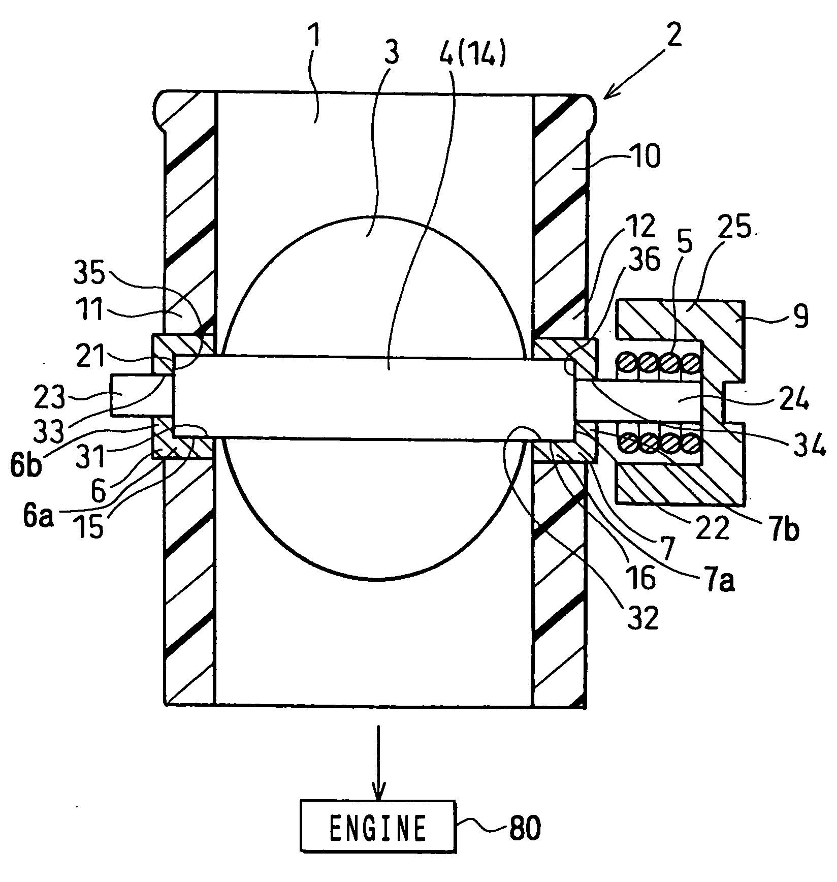
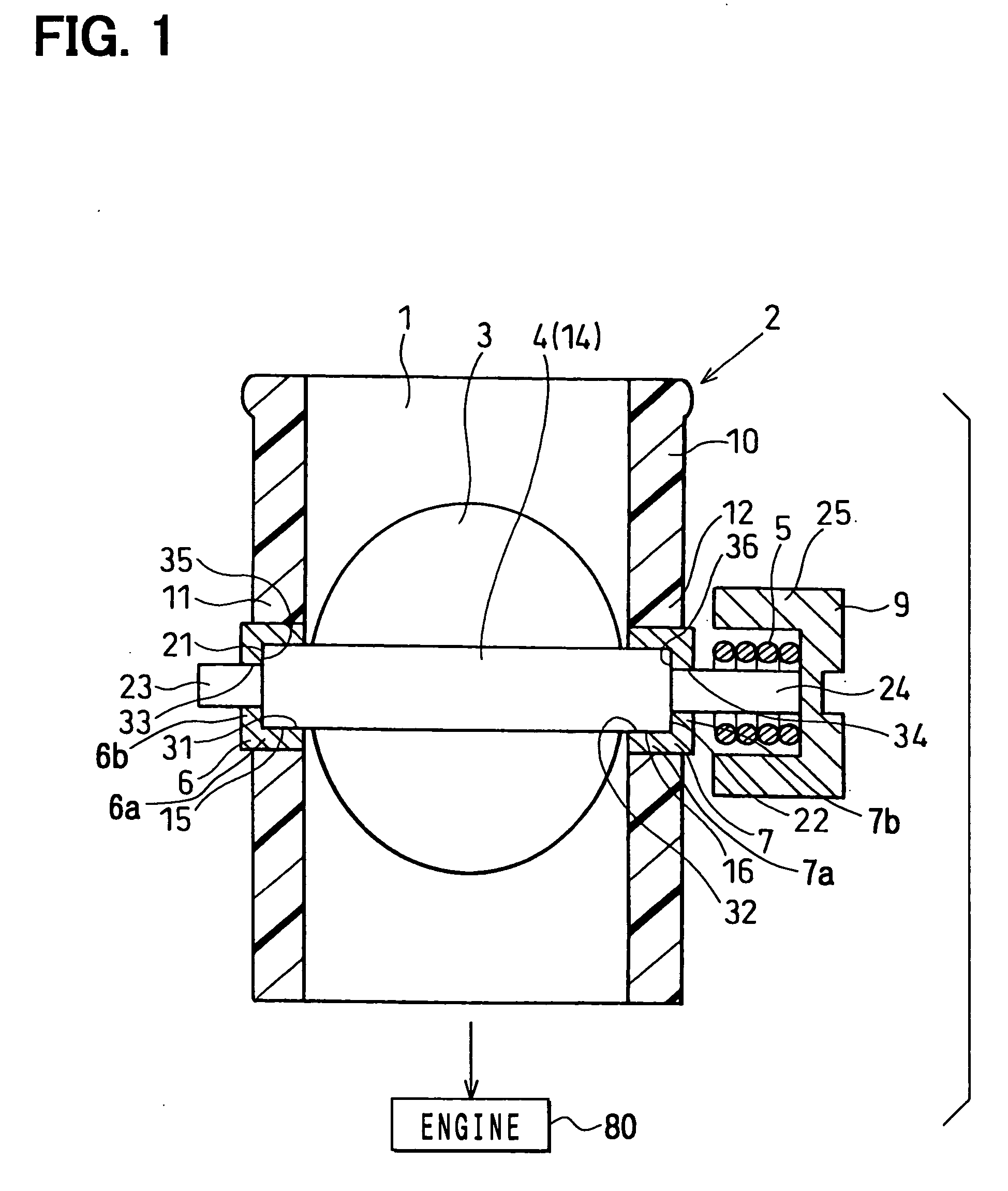
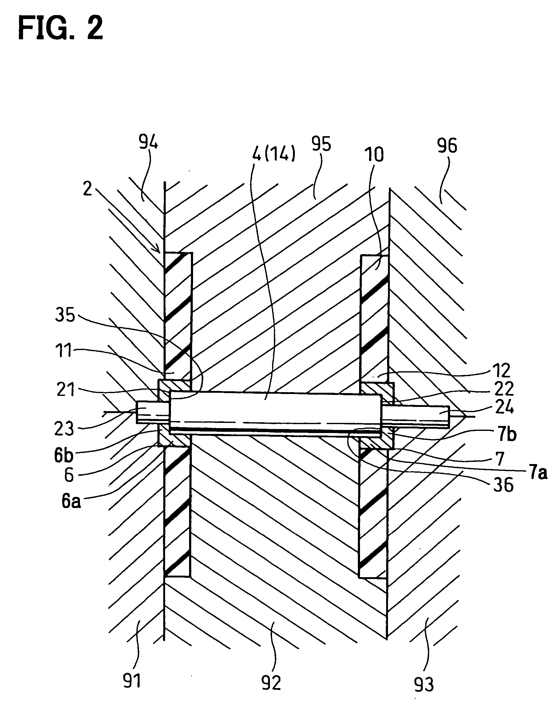
[0022] As shown in FIGS. 1 to 2, a throttle apparatus is constructed with a throttle body 2, a throttle valve 3, a throttle shaft 4, a power unit (not shown), a return spring 5, and an ECU (electronic control unit, not shown).
[0023] The throttle body 2 internally forms an intake air passage 1 introducing intake air into cylinders of an internal combustion engine 80, such as a gasoline engine. The throttle valve 3 controls an amount of intake air flowing through the intake air passage 1 toward the cylinders of the engine 80. The throttle shaft 4 is arranged to radially penetrate the throttle body 2, so that the throttle shaft 4 is rotatably supported by the throttle body 2.
[0024] The power unit serves as a valve actuating means to rotate the throttle valve 3 in an open direction, in which the throttle valve 3 is opened to be in a full throttle position (full open position), or a close direction, in which the throttle valve 3 is closed to be in an idling po...
Example
[0059] (Second Embodiment)
[0060] As shown in FIG. 3A, a circumferential groove (second bearing restricting means) 41 is formed in the outer circumferential face of the second cylindrical portion 7a of the second bearing 7, in this embodiment. Therefore, when the throttle body 2 is molded of a resinous material, filler (molten resinous material) forming the inner circumferential periphery of the second hole of the second boss portion 12 of the throttle body 2 flows into the circumferential groove 41 of the second bearing 7. Accordingly, adhesive strength, i.e., joint strength between the resinous material forming the throttle body 2 and the second bearing 7 can be enhanced, so that the second bearing 7 can be restricted from moving axially and rotating circumferentially with respect to the second boss portion 12 of the throttle body 2. Furthermore, a circumferential groove (first bearing restricting means, not shown) can be formed in the outer circumferential face of the first cylin...
Example
[0066] (Third Embodiment)
[0067] As shown in FIG. 4, in the third embodiment, a circular first restricted portion 26 is integrally formed on one end side, i.e., first end side of the throttle shaft 4 on the left side in FIG. 4. The first supported portion (first step portion) 26 is located on the axially end side outwardly with respect to the first sliding portion 15 of the throttle shaft 4, and supported by a first supporting portion 37 of the first bearing 6. The first bearing 6 is constructed with a first cylindrical portion 6a, a first annular portions 6b and the like. The first cylindrical portion 6a of the first bearing 6 is provided inside the first hole formed in the first boss portion 11 of the throttle body 2. The first annular portion 6b plugs axially one end side, i.e., first end side of the first cylindrical portion 6a on the left side in FIG. 4.
[0068] The first supporting portion 37 is integrally formed on the axially bottom wall face of the first annular portion 6b t...
PUM
 Abstract
Description
Claims
Application Information