Encapsulating packets into a frame for a network

Active Publication Date: 2005-03-24
RAYTHEON CO
View PDF10 Cites 28 Cited by
  • Summary
  • Abstract
  • Description
  • Claims
  • Application Information

AI Technical Summary

Benefits of technology

In accordance with the present invention, disadvantages and problems associated with p

Problems solved by technology

Known techniques, however, typically cannot effectively and efficiently encapsulate packets into frames.
For example, known techniques, may suffer from high overhead f

Method used


Image

  • Encapsulating packets into a frame for a network
  • Encapsulating packets into a frame for a network
  • Encapsulating packets into a frame for a network

Examples


Example

DETAILED DESCRIPTION OF THE DRAWINGS

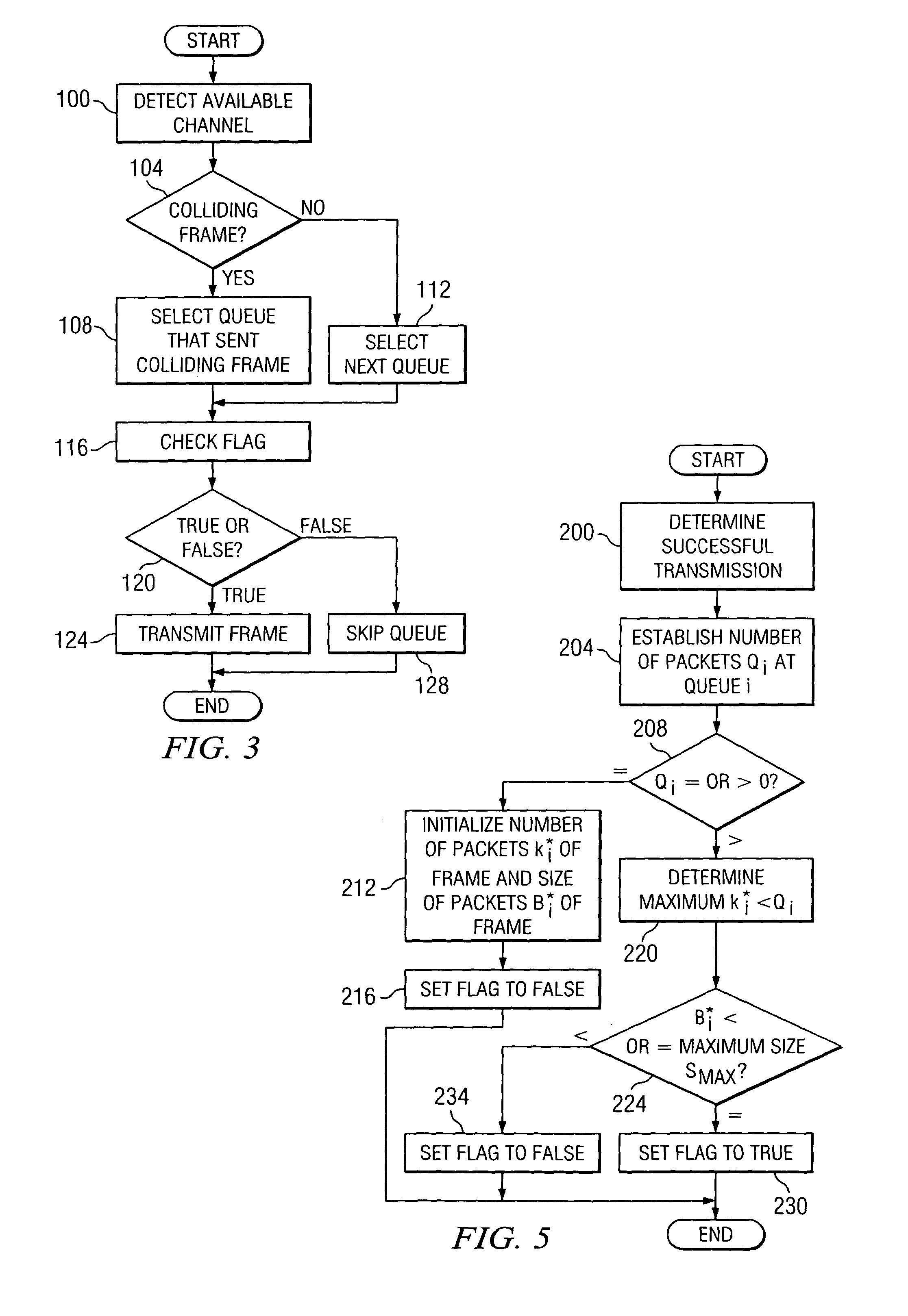
Embodiments of the present invention and its advantages are best understood by referring to FIGS. 1 through 7 of the drawings, like numerals being used for like and corresponding parts of the various drawings.

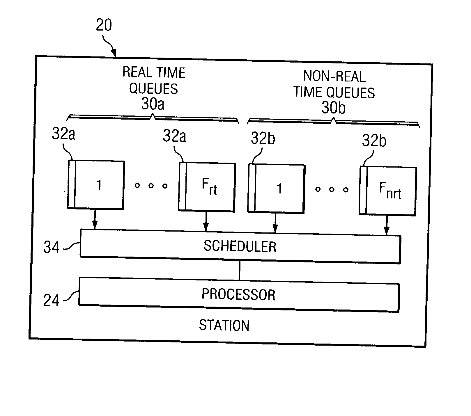
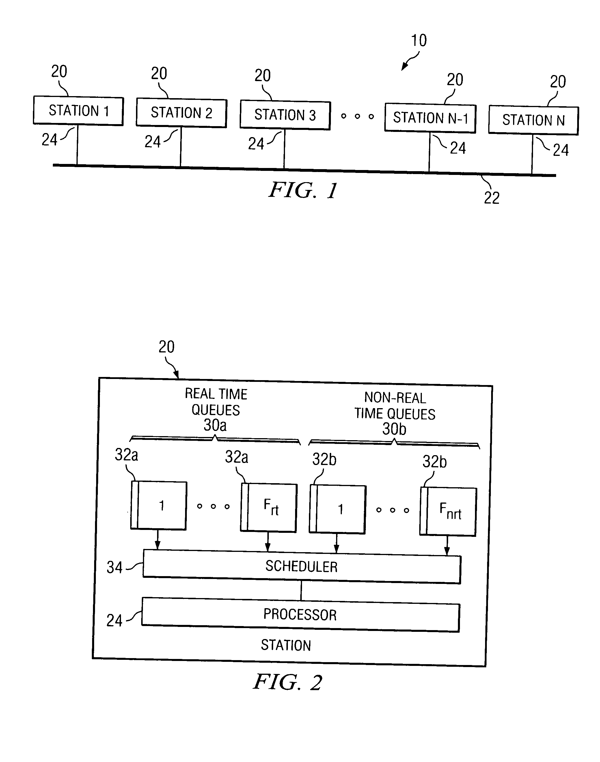
FIG. 1 is a block diagram illustrating one embodiment of a system 10 for encapsulating packets into a frame. In general, system 10 manages the number of packets encapsulated into a frame depending upon the delay requirements of the packets and network activity. A larger payload typically yields higher bandwidth efficiency, but also results in longer transmission delays, which may violate the delay requirements of the packets. Accordingly, system 10 attempts to maximize bandwidth efficiency subject to the delay requirements of the packets.

According to the illustrated embodiment, system 10 includes one or more stations 20 coupled to a link 22. A station 20 may comprise an Ethernet station that receives packets from an upper Internet Protoc...


PUM


Abstract

Encapsulating packets into a frame includes receiving the packets at a station of a number of stations of a network. Each packet is associated with a delay requirement that reflects a deadline corresponding to at least one of the stations. The packets are directed to queues of the station. An available channel of the network is detected. It is determined that one or more packets at a queue are ready to be encapsulated into a frame in accordance with the delay requirements. The one or more packets are encapsulated into the frame for transmission using the available channel.

Description

TECHNICAL FIELD OF THE INVENTION This invention relates generally to the field of data communication and more specifically to encapsulating packets into a frame for a network. BACKGROUND OF THE INVENTION According to network protocols, packets at a given layer may be encapsulated into frames at a lower layer in order to transmit the packets from one node to another node of a network. Known techniques provide for encapsulating individual Internet Protocol (IP) packets within individual Ethernet frames. Known techniques also provide for supporting the transmission of real-time traffic over a network. For example, a known technique may use forward error correction (FEC) to provide quality-of-service (QoS) guarantees for real-time traffic. Known techniques, however, typically cannot effectively and efficiently encapsulate packets into frames. For example, known techniques, may suffer from high overhead for small sized packets. Also, known techniques may not be able to provide continuo...

Claims


Application Information

Patent Timeline
IPC IPC(8): H04L47/43H04L12/413H04L12/56
CPCH04L12/5693H04L47/13H04L47/2416H04L47/2441H04L47/283H04L49/9094H04L47/522H04L47/564H04L47/6215H04L47/626H04L49/90H04L47/36H04L47/50H04L47/56H04L47/28
Inventor ROSENGARD, PHILLIP I.KRUNZ, MARWAN M.
Owner RAYTHEON CO
Why Eureka
Try Eureka