Bottle crate

Inactive Publication Date: 2005-03-31
REHRIG PACIFIC CO INC
View PDF24 Cites 14 Cited by
  • Summary
  • Abstract
  • Description
  • Claims
  • Application Information

AI Technical Summary

Benefits of technology

[0007] It is an object according to the present invention to provide an improved c

Problems solved by technology

Crates under these conditions may eventually fail due

Method used


Image

  • Bottle crate
  • Bottle crate
  • Bottle crate

Examples


Example

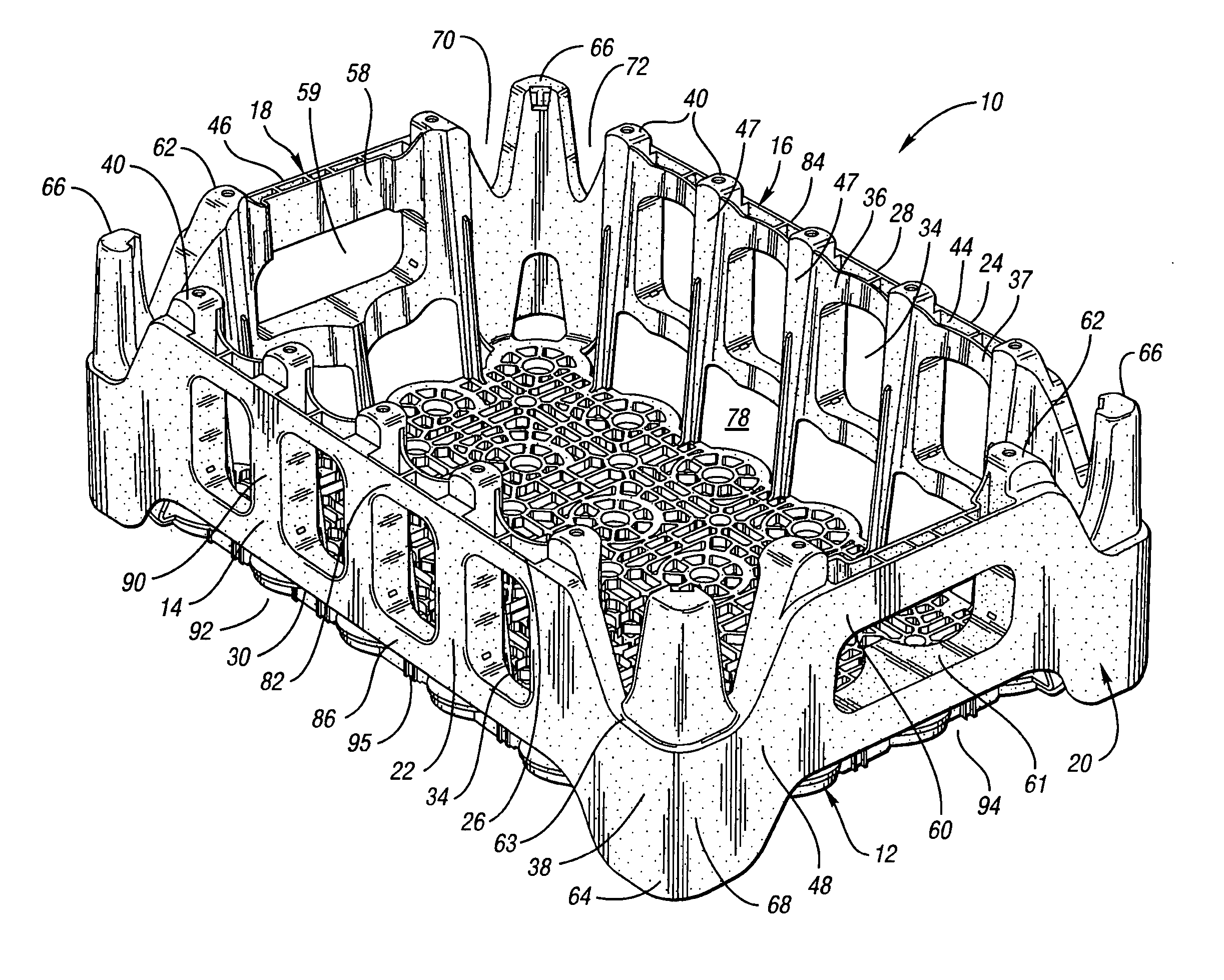
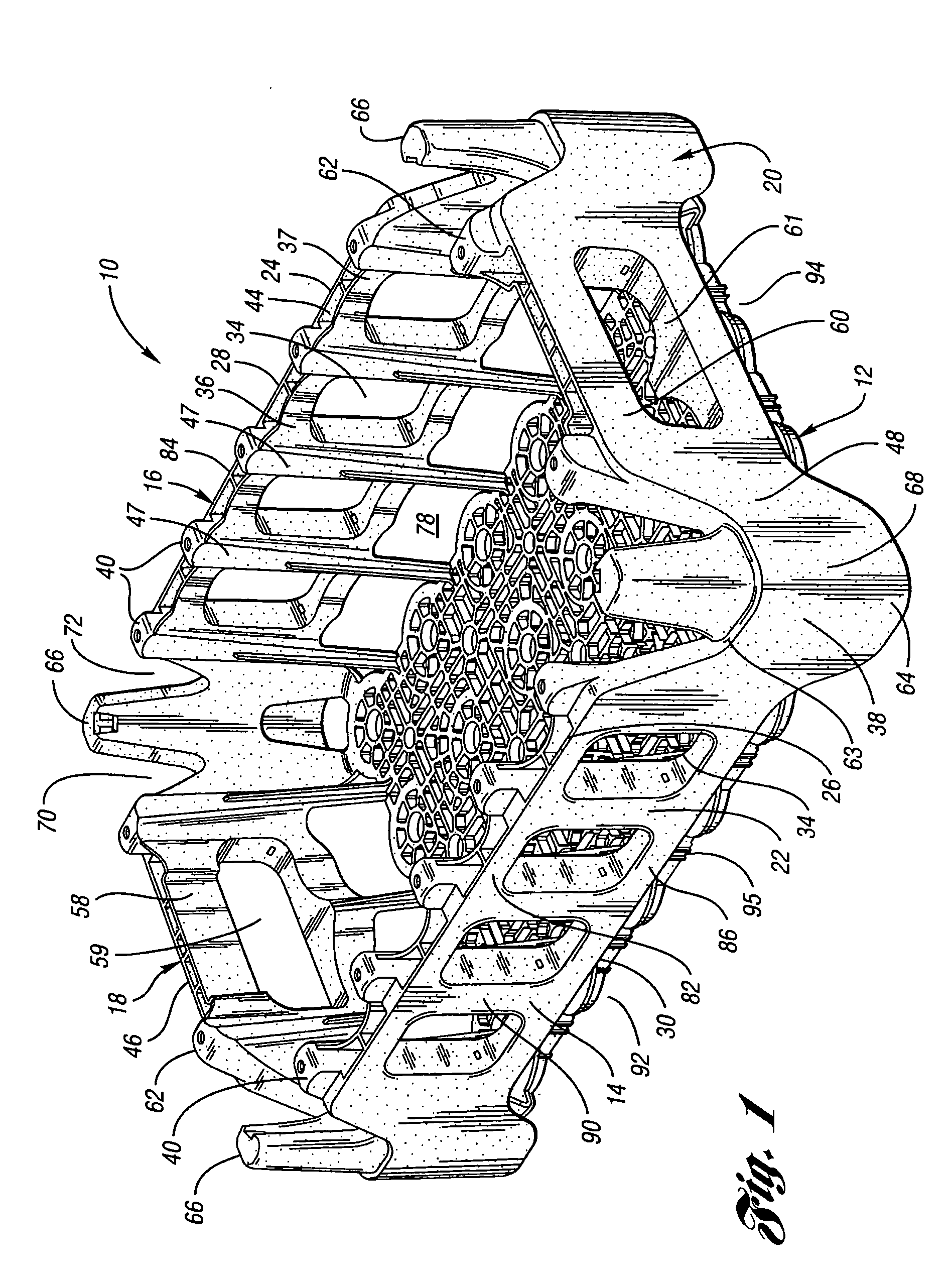
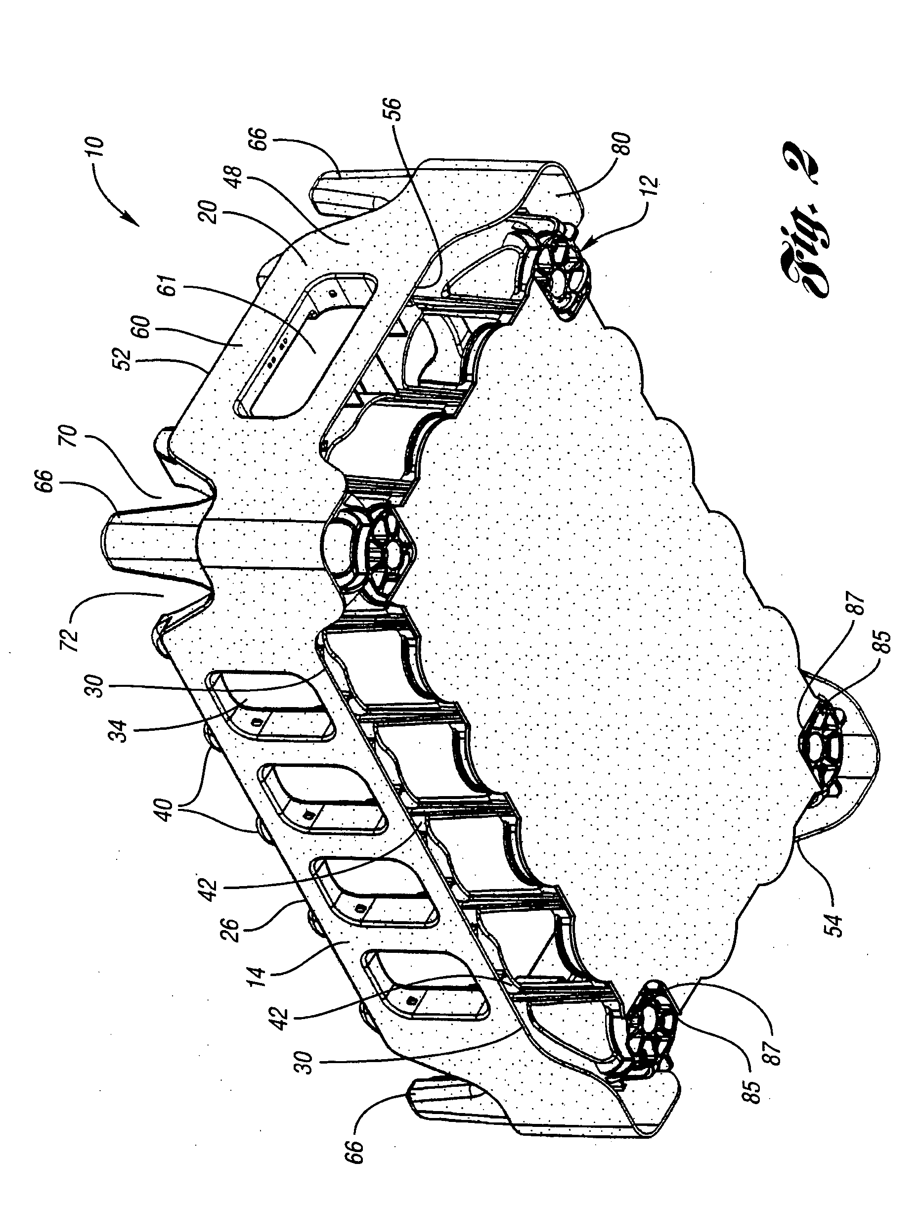
[0038] With references to FIGS. 1-8 of the drawings, illustrated is a first embodiment of a bottle crate 10 according to the present invention. Crate 10 may also be referred to as a tray, container or case, and is formed of a plastic material and preferably a thermoplastic material. Crate 10 includes a floor member or base 12, a first pair of opposed sidewalls 14,16 and a second pair of opposed sidewalls 18,20. For ease of reference, the second pair of opposed sidewalls 18,20 is referred to herein as a pair of end walls 18,20. Sidewalls 14,16, end walls 18,20 and floor member 12 are integrally formed with each other in order to define a compartment therein. As best illustrated in FIGS. 1 and 3, floor member 12 is inwardly offset from the planes of each sidewall 14,16 and end wall 18,20.

[0039] Sidewalls 14,16 include a band member 22,24 defined by an upper edge 26,28 and a lower edge 30,32. In a preferred embodiment, sidewalls 14,16 include one or more openings or windows 34 corresp...

Example

[0051]FIG. 14 illustrates a second embodiment of the bottle crate, designated as bottle crate 110, according to the present invention. The features of crate 110 corresponding to those of the first embodiment shall have like reference numerals with the addition of a “1” prefix. Bottle crate 110 is generally similar to bottle crate 10, however, bottle crate 110 has a solid upper edge 126,128. While sidewalls 114,116 and end walls 118,120 generally have a double wall thickness, directly below sidewall upper edges 126,128, the outer surface 141 is open such that the upper inner surface 143 forming the upper curved bottle support area has a single wall thickness.

[0052] With reference to FIGS. 15a through 19, illustrated therein is a third embodiment of a bottle crate 210 according to the present invention. The features of crate 210 corresponding to those of the first embodiment shall have like reference numerals with the addition of a “2” prefix. Accordingly, crate 210 includes a floor ...

Example

[0059] With reference to FIG. 21, shown is a perspective view of a third embodiment of bottle crate 310 according to the present invention. The features of crate 310 corresponding to those of the first embodiment shall have like reference numerals with the addition of a “3” prefix. As illustrated therein, corner portions 338 are offset inwardly and recessed from the planes defined by the side wall band members 322,234 and the end wall band members 346,348. This design thereby reduces stress in corner areas 338, such that load transfer would be almost completely in the band members. The stresses to which the crate is subjected to by the aforementioned automated handling equipment would also be placed upon the band members.

[0060] While embodiments of the invention have been illustrated and described, it is not intended that these embodiments illustrate and describe all possible forms of the invention. Rather, the words used in the specification are words of description rather than li...


PUM


Abstract

A nestable crate for bottles which includes a floor member and first and second pairs of opposed sidewalls integrally formed with the floor member. Each sidewall includes a side band member which is defined by a centrally disposed upper edge and lower edge. The lower edge is spaced above the floor member by a predetermined distance to define a sidewall nesting area therebelow. The upper and lower edges each contoured downwardly to form a corner band portion having a corner upper edge and corner lower edge, wherein each nesting area matingly receives a corresponding side band member of a crate nested subjacent thereto.

Description

CROSS-REFERENCE TO RELATED APPLICATION [0001] This is a continuation of co-pending application Ser. No. 09 / 626,517 filed Jul. 27, 2000, entitled “Bottle Crate”.TECHNICAL FIELD [0002] This invention relates to a bottle crate. BACKGROUND ART [0003] Generally, beverage bottles go through a bottle facility and are loaded into trays which are then palletized. A pallet may include multiple layers of trays of a single product, such as soft drinks or beer of the same brand. Trays in successive layers are stacked or cross-stacked on top of each other, with the bottles bearing most of the load of the above-stacked trays. These bulk pallets are then typically stored in a warehouse for shipping to retailers. [0004] One recent advance in the distribution area is a use of a product handling device known as the Tygard Claw® manufactured by Tygard Machine and Manufacturing Company of Pittsburgh, Pa. The Tygard Claw can be installed to the front or the side of a conventional fork lift carriage, and ...

Claims


Application Information

Patent Timeline
IPC IPC(8): B65D1/22B65D21/02
CPCB65D1/22B65D2501/24019B65D21/0212
Inventor KOEFELDA, GERALD R.APPS, WILLIAM P.
Owner REHRIG PACIFIC CO INC
Why Eureka
Try Eureka