Stabilizer device
- Summary
- Abstract
- Description
- Claims
- Application Information
AI Technical Summary
Benefits of technology
Problems solved by technology
Method used
Image

Examples
first embodiment
[0031] the present invention will be described below using FIGS. 1 through 5.
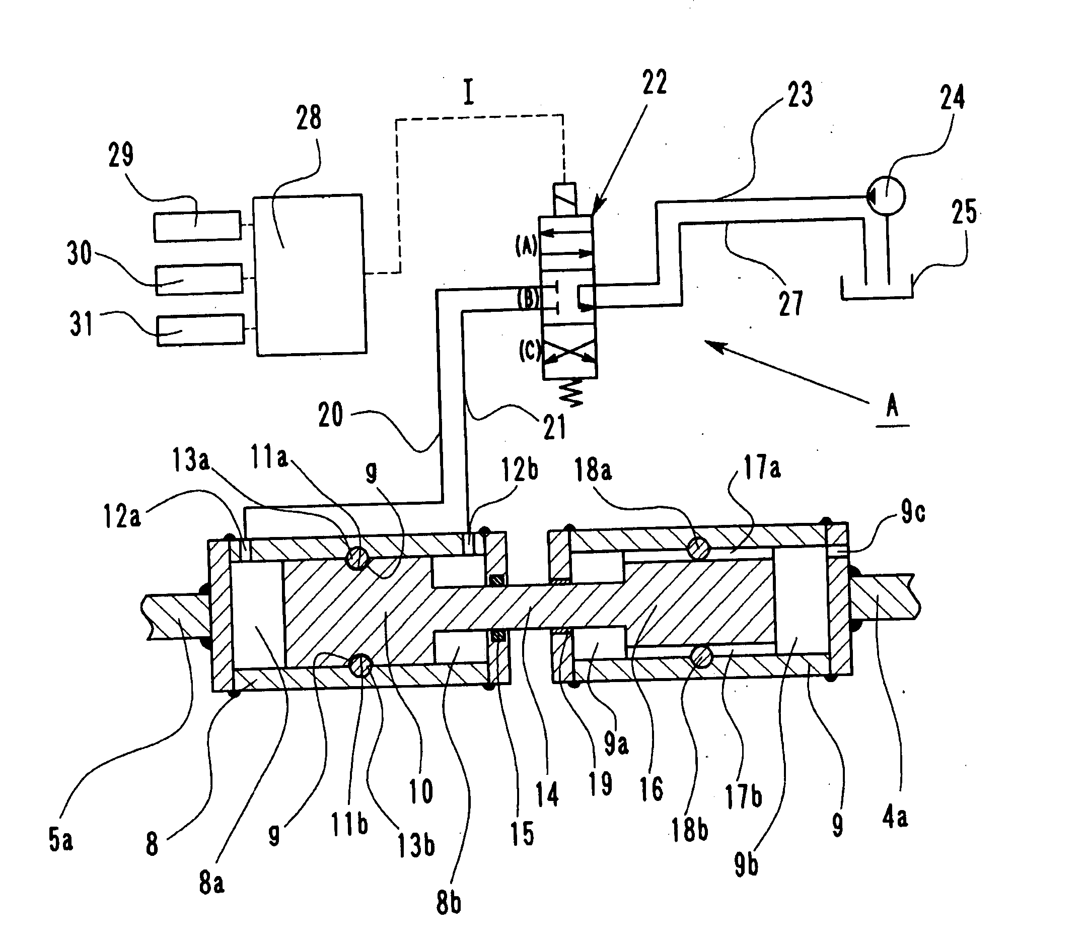
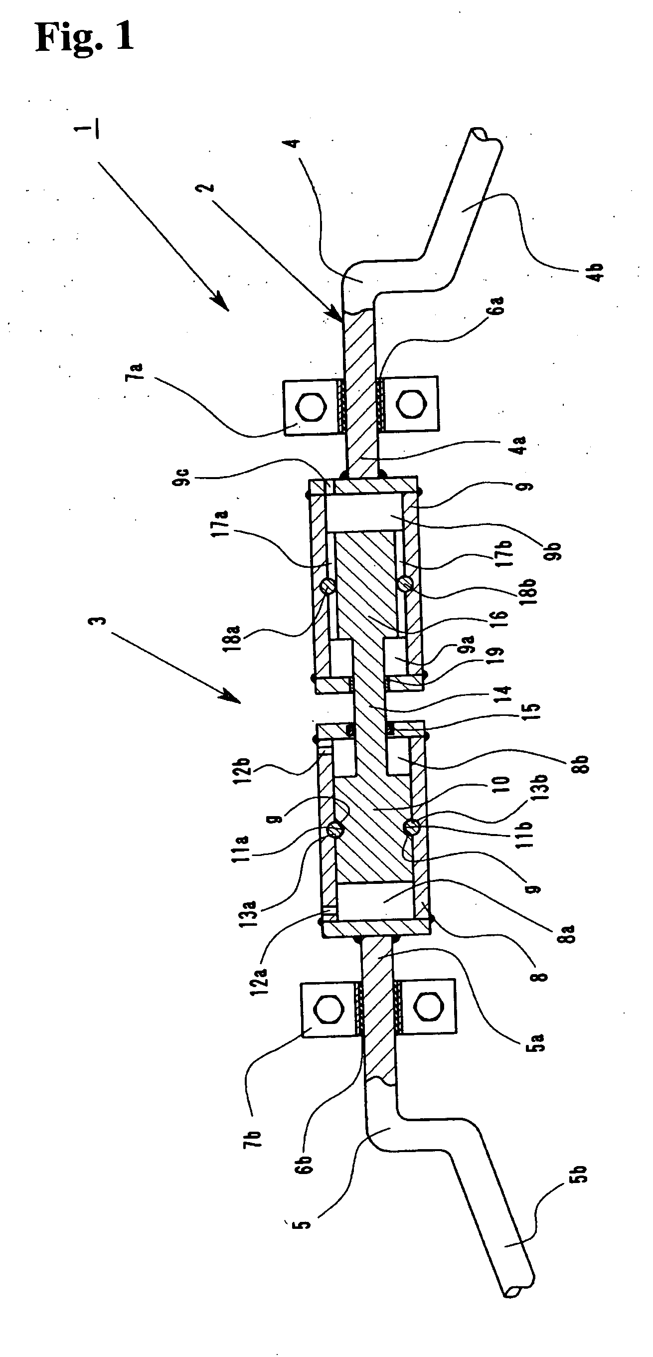
[0032] A stabilizer device 1 is attached to the vehicle body between the left and right wheel shafts of the vehicle (none of which are shown in the drawing) It comprises a stabilizer 2 formed from flexible spring steel and an actuator 3. The stabilizer 2 is comprised of two parts, a first stabilizer 4 and a second stabilizer 5, located respectively at both ends of a shaft portion which is mounted substantially at the center of the vehicle body.
[0033] The first stabilizer 4 and second stabilizer 5 are comprised of shaft portions 4a and 5a and arm portions 4b and 5b, respectively. The stabilizers 4 and 5 are bent at the respective ends of the shaft portions 4a and 5a, as shown in the drawing, so that the other ends thereof (not shown) can be attached to the left and right wheel shafts of the vehicle, respectively.
[0034] The shaft portion 4a of the first stabilizer 4 and the shaft portion 5a of the second st...
second embodiment
[0077] Next, the present invention will be described using FIGS. 6 and 7.
[0078] Note that for convenience, parts identical to those of the first embodiment have been referenced with the same reference numbers and symbols, and description thereof will be omitted.
[0079] A stabilizer device 50 according to the second embodiment has the first cylinder which is constructed differently than that of the stabilizer device 1 of the first embodiment described above.
[0080] A first cylinder 52 (cylinder) is provided in an actuator 51, and a piston 53, which divides the first cylinder 52 into two cylinder chambers 52a and 52b, is provided in the first cylinder 52. Spiral grooves 54a and 54b are formed in the circumference of the piston 53 in a similar manner to those formed in the piston 10 of the first embodiment.
[0081] Rigid balls 55a and 55b are partially and rotatably inserted in the inner peripheral wall of the first cylinder 52 at a position substantially bisecting the cylinder in the a...
third embodiment
[0088] Next, the present invention will be described using FIG. 8.
[0089] Note that for convenience, parts identical to those of the first embodiment have been referenced by the same reference numbers and symbols, and description thereof will be omitted.
[0090] A stabilizer device 60 according to the third embodiment differs from the stabilizer device 1 of the first embodiment in that oil is also supplied to and discharged from the second cylinder provided in the actuator, the bearing member for mounting the stabilizer device on the vehicle body is modified, and a bearing member is provided between the first cylinder and the second cylinder to support the two cylinders in a manner that enables the two cylinders to rotate relatively in the axial direction.
[0091] A second cylinder 62 is provided in an actuator 61, and a piston 63 (second piston), which divides the second cylinder 62 into two cylinder chambers 62a and 62b, is provided in the second cylinder 62. Grooves 64a and 64b exte...
PUM
 Abstract
Description
Claims
Application Information
 - R&D
- Intellectual Property
- Life Sciences
- Materials
- Tech Scout
- Unparalleled Data Quality
- Higher Quality Content
- 60% Fewer Hallucinations
Browse by: Latest US Patents, China's latest patents, Technical Efficacy Thesaurus, Application Domain, Technology Topic, Popular Technical Reports.
© 2025 PatSnap. All rights reserved.Legal|Privacy policy|Modern Slavery Act Transparency Statement|Sitemap|About US| Contact US: help@patsnap.com