
Select logic for low voltage swing circuits

a low-voltage swing circuit and signal circuit technology, applied in logic circuits, pulse techniques, digital storage, etc., can solve the problems of slowing down the operation of lvs circuits, lvs circuits may not be able to overcome reverse differentials, and functional failure of integrated circuits

Inactive Publication Date: 2005-03-31
INTEL CORP
View PDF14 Cites 10 Cited by
  • Summary
  • Abstract
  • Description
  • Claims
  • Application Information

AI Technical Summary

Benefits of technology

The present invention relates to electronic devices and in particular, low-voltage-swing circuits for logic evaluation. The invention aims to address the issue of reverse differential build-up in low-voltage-swing circuits and proposes a solution to prevent this problem. The invention uses precharged-low dynamic selects as an input to the low-voltage-swing circuit, which helps to overcome the reverse differential build-up issue. The invention also includes a master-slave flip-flop to speed up the turning-OFF edge of the select signals and minimize the number of buffer stages between the flip-flop and the LVS circuit. Overall, the invention improves the performance and reliability of low-voltage-swing circuits in electronic devices.

Problems solved by technology

In such a case, this phenomenon slows down the operation of the LVS circuit.
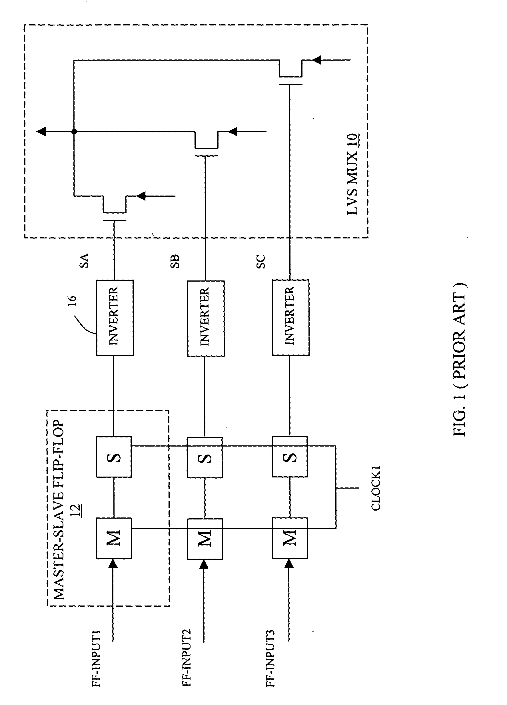
If a pulsed clock system is used to clock the LVS circuit and the contention period is significant, then the LVS circuit may not be able to overcome the reverse differential and a functional failure of an integrated circuit (e.g. a microprocessor) containing the LVS circuit may occur.
However, a dynamic select is not a viable solution if the LVS circuit is distributed over a large distance, because in this case the LVS select maximum and minimum timing window is non-existent (negative) for sufficiently fast target frequencies.
Furthermore, a dynamic signal distributed across a long distance is susceptible to pulse evaporation if the clock period is sufficiently short (high target frequency).

Method used


Image

  • Select logic for low voltage swing circuits
  • Select logic for low voltage swing circuits
  • Select logic for low voltage swing circuits

Examples


Embodiment Construction

[0018] In the following description, for purposes of explanation, numerous details are set forth in order to provide a thorough understanding of the disclosed embodiments of the present invention. However, it will be apparent to one skilled in the art that these specific details are not required in order to practice the disclosed embodiments of the present invention. In other instances, well-known electrical structures and circuits are shown in block diagram form in order not to obscure the disclosed embodiments of the present invention.

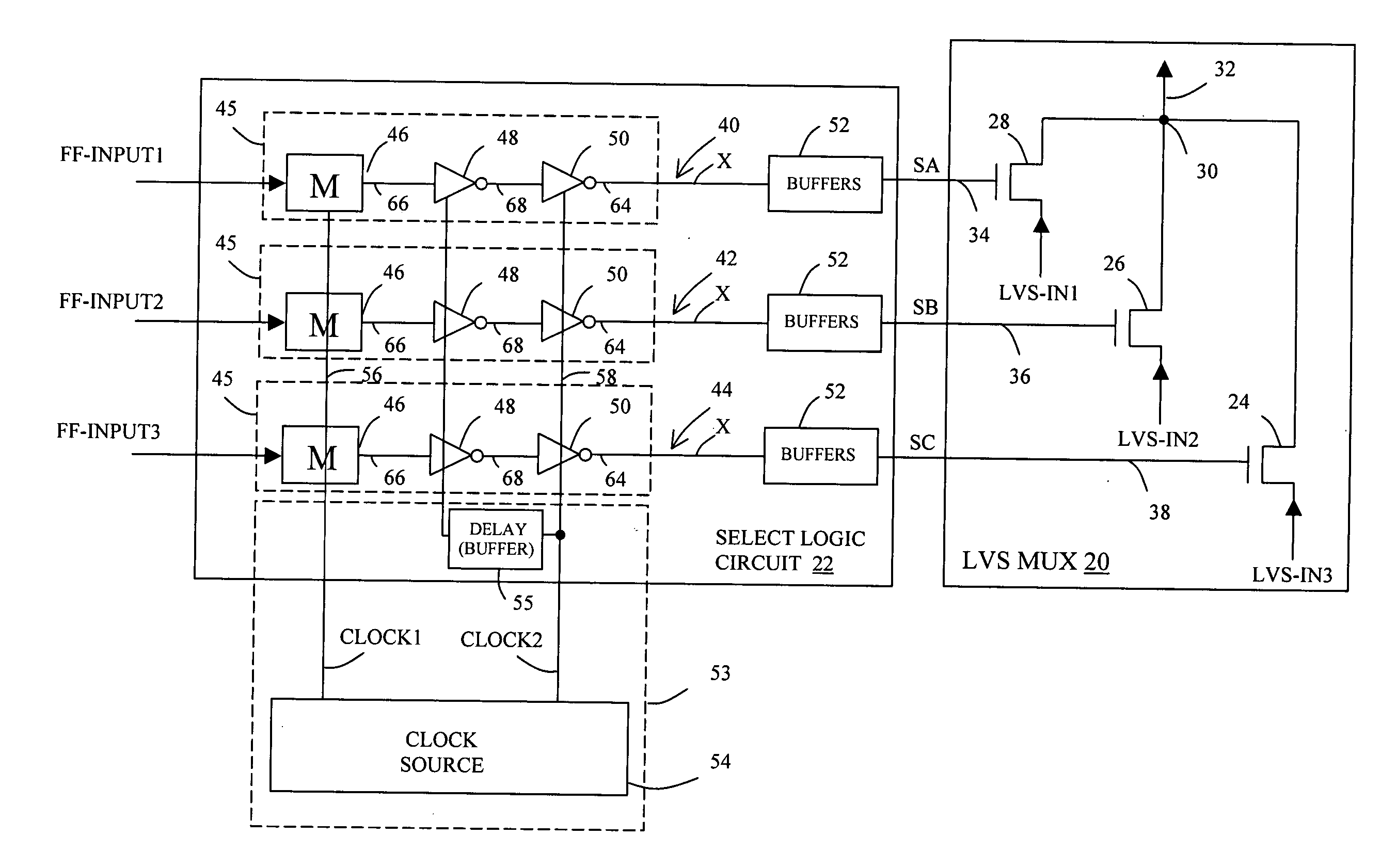
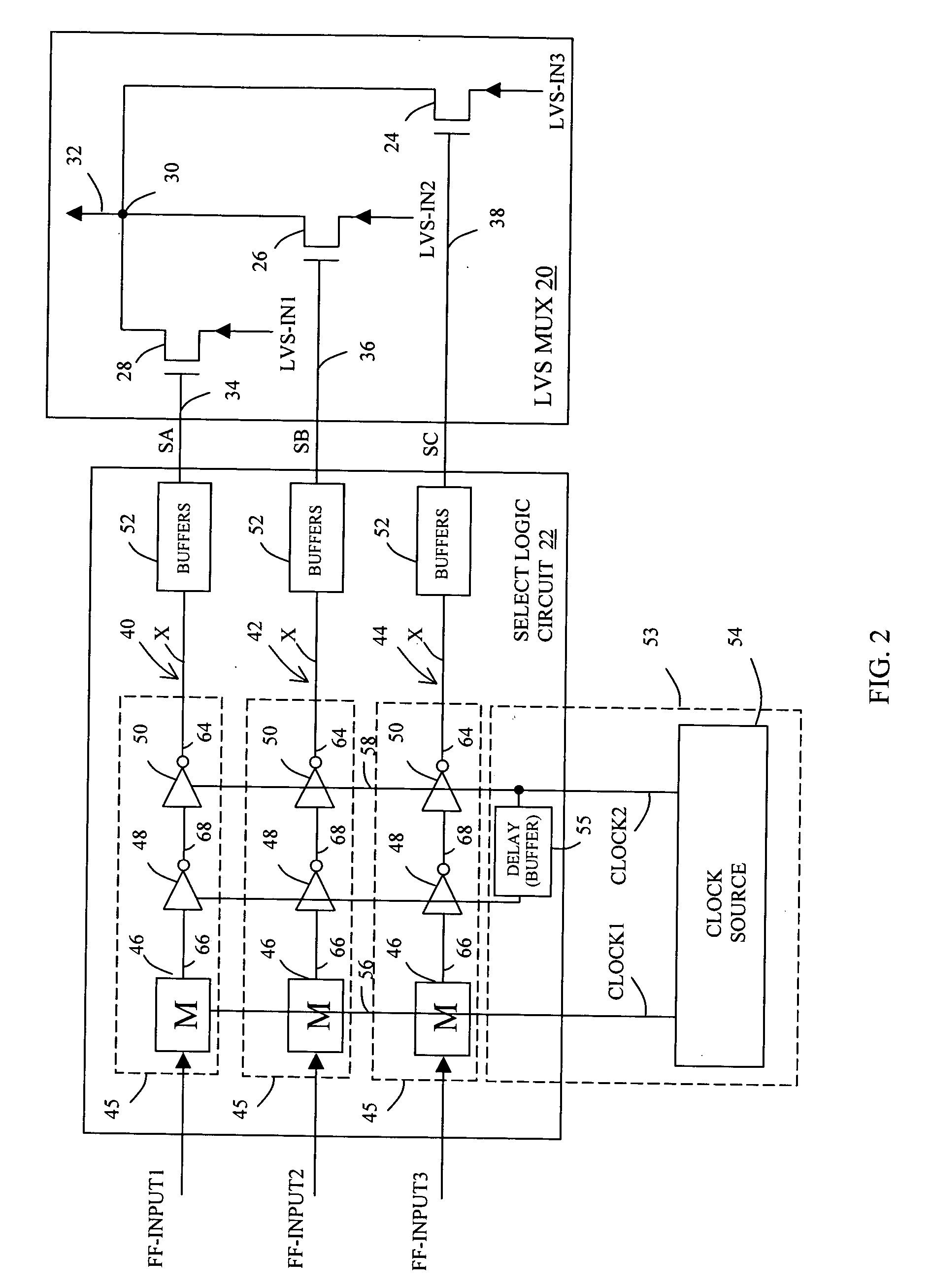
[0019] With reference to FIG. 2, there is shown an illustrative low voltage swing (LVS) circuit 20 with a select logic circuit 22 in accordance to one embodiment of the present invention. Although many possible LVS circuits may be used with this select logic circuit 22, the illustrative LVS circuit 20 is a 3:1 multiplexer having three n-channel (NFET) transistors 24, 26, and 28 with their source terminals coupled to input signals LCS-IN1, LCS-IN2, a...


PUM


Abstract

An apparatus comprising a low voltage swing (LVS) circuit having a plurality of alternating LVS pre-charging and evaluation phases and a select logic circuit coupled to the LVS circuit and responsive to a plurality of input data signals to generate a plurality of select signals for the LVS circuit. Each of the select signals occurs during one of the LVS evaluation phases and has a turning-on edge and a turning-off edge. The turning-off edge of each of the select signals is generated independent of the input data signals.

Description

BACKGROUND OF THE INVENTION [0001] 1. Field of the Invention [0002] The present invention relates to electronic devices, and in particular, to select signal circuits for low voltage swing circuits. [0003] 2. Description of Related Art [0004] Low-voltage-swing (LVS) circuits have been developed as a means to decrease circuit area, increase throughput and consume less power than other circuit families. LVS circuits utilize large networks of pre-charged dual rail gates with low voltage outputs and sense amplifiers to restore the output to full rail signals. In contrast to full-voltage swing circuits, a low-voltage-swing logic circuit may provide valid data output signals based on a relatively small difference in potential between a pair of complementary data input signals. More specifically, a first data wire is used to carry a true value of the valid data signal and a second data wire is used to carry a complementary value of the same valid data signal. In a two-phase clocking arrange...

Claims


Application Information

Patent Timeline
Patent Type & Authority Applications(United States)
IPC IPC(8): H03K3/012H03K3/037H03K3/3562
CPCH03K3/012H03K3/35625H03K3/0372
Inventor WIJERATNE, SAPUMAL
Owner INTEL CORP
Learn More