Biased door retaining assembly

Inactive Publication Date: 2005-04-07
NANTAIS PAUL
View PDF9 Cites 2 Cited by
  • Summary
  • Abstract
  • Description
  • Claims
  • Application Information

AI Technical Summary

Benefits of technology

[0013] Advantages of the present invention are: fewer components, cheaper to manufacture, less complex therefore easy to assemble, easy

Problems solved by technology

These methods of securement vary from placing a variety of objects in front of the door to hold it open, to traditional door stops that are mounted to the door and engage against the floor itself preventing the door from closing but they do not stop the door from hitting the wall.
However, prior art devices are often complex i

Method used


Image

  • Biased door retaining assembly
  • Biased door retaining assembly

Examples


Embodiment Construction

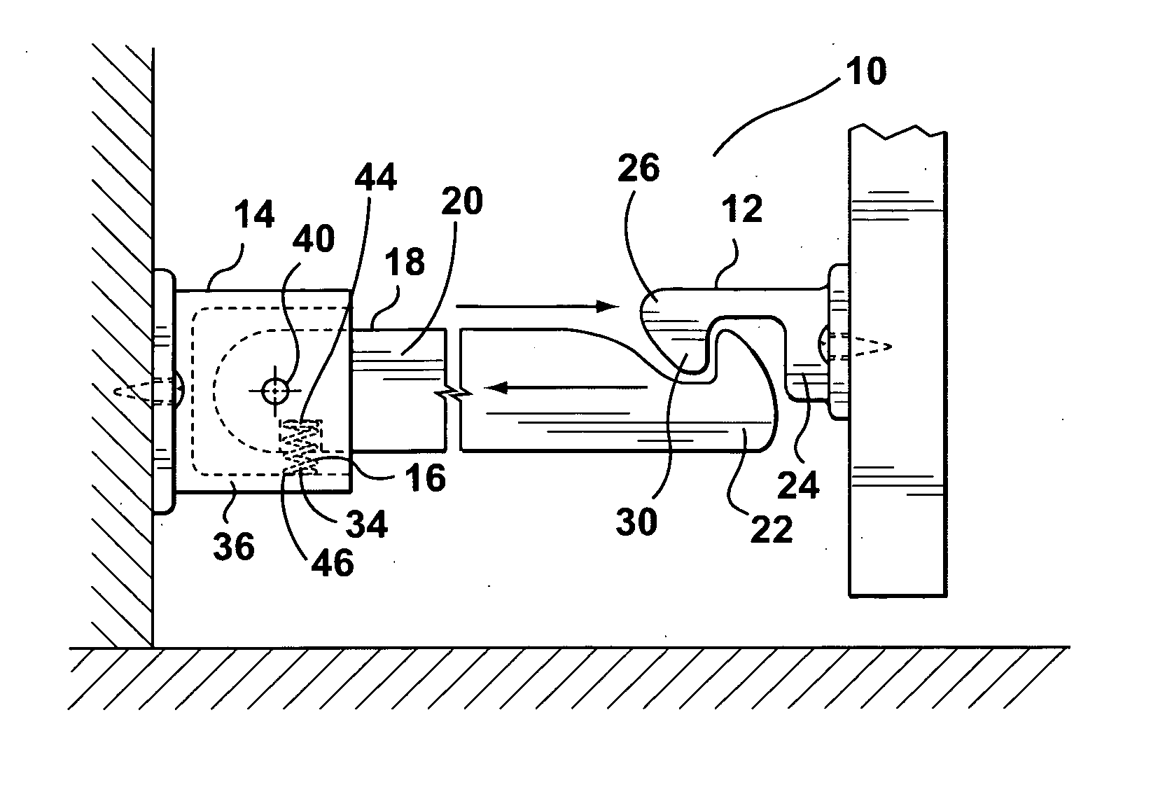
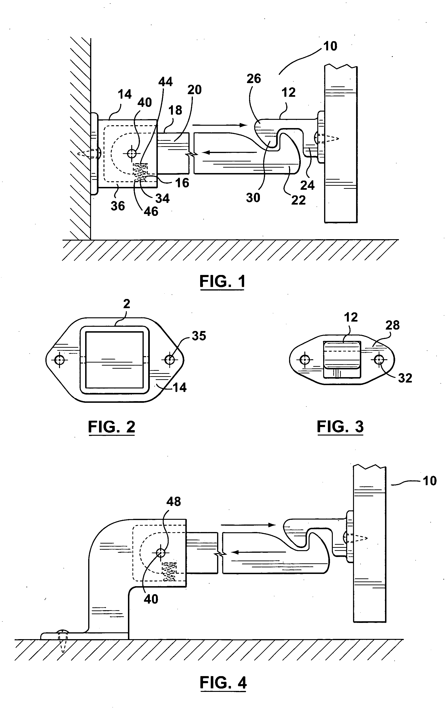
[0020] Referring to FIGS. 1 and 4, there is illustrated in a side elevational view, a biased door retaining assembly 10 in accordance with the preferred embodiment of the present invention. The biased door retaining assembly 10 includes a hook member 12, a support assembly 14 having a biasing means 16 and an arm 18 having a first end 20 and a second end 22.

[0021] Referring to FIGS. 1 and 3, the hook member 12 may further comprise of a first end 24 and a second end 26. The first end 24 may have a mounting portion 28 and the second end 26 may have a hook portion 30. The mounting portion 28 may be configured a variety of ways so as to allow the hook member 12 to be mounted to different surfaces. For example, the mounting portion 28 may be a straight configuration to mount on a wall or door, or the mounting portion 28 may be curved so as to mount on the floor.

[0022] The mounting portion 28 may also include a series of holes 32 that allow the mounting portion 28 to be mounted on these ...


PUM


Abstract

A biased door retaining assembly including a hook member, a support assembly having a biasing means, and an arm having a first end and a second end. The support assembly and the biasing means may engage the first end of the arm biasing the arm in a first direction. The second end of the arm is adapted to engage the hook member.

Description

FIELD OF THE INVENTION [0001] This invention relates in general to retaining devices such as a door stop and more particularly to a biased door retaining assembly. BACKGROUND OF THE INVENTION [0002] There are numerous methods available to secure or retain a door in different positions. These methods of securement vary from placing a variety of objects in front of the door to hold it open, to traditional door stops that are mounted to the door and engage against the floor itself preventing the door from closing but they do not stop the door from hitting the wall. [0003] Prior art door stops have been devised to address some of the below noted problems. For example, U.S. Pat. No. 4,159,837, which issued on Jul. 3, 1979 to Morita relates to the combination of a door stop and releasable latching device, whereby a keeper member is mounted to a conventional door and positioned thereon to engage a stationary door stop having a latching mechanism coupled therewith. The door stop comprises a...

Claims


Application Information

Patent Timeline
IPC IPC(8): E05F5/00E05F5/06
CPCY10T16/625E05F5/06
Inventor NANTAIS, PAUL
Owner NANTAIS PAUL
Why Eureka
Try Eureka