

Displacement control unit device and functional platform system
A manipulation unit, displacement technology, applied in electrical components, piezoelectric effect/electrostrictive or magnetostrictive motors, generators/motors, etc. The advantages of output displacement accuracy cannot be fully utilized, etc., to achieve good motion orientation and continuity, fewer components, and avoid complex effects
- Summary
- Abstract
- Description
- Claims
- Application Information
AI Technical Summary
Problems solved by technology
Method used
Image

Examples
Embodiment 1
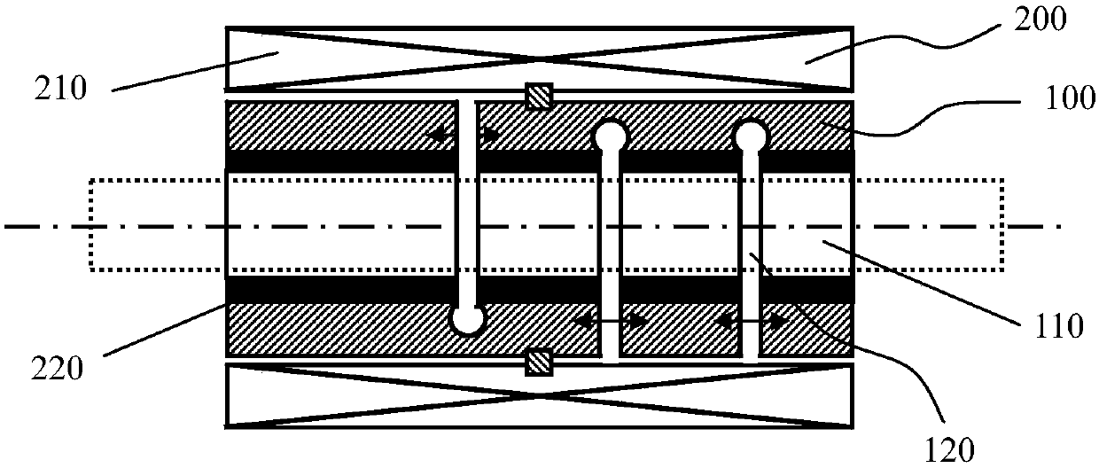
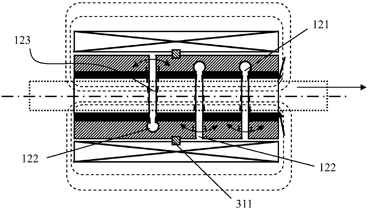
[0104] Such as figure 1 As shown, the deformation actuator 100 has an elastic structure, and the deformation actuator 100 is provided with three opening and closing grooves 120 , and the three opening and closing grooves 120 all pass through the side of the deformation actuator 100 . It includes two driving slots 122 and one clamping slot 121 , and the two driving slots 122 constitute the driving group 123 . The driving deformation structure 200 includes a driving electromagnet 210 and an operating magnet 220. The driving electromagnet 210 is installed on the provided casing, and the operating magnet 220 is directly installed on the deformation actuator 100. The deformation actuator 100 is located on two The part between the driving grooves 122 is axially fixed on the housing through a limiting block 311 . Preferably, the limiting block 311 is annular in shape. Preferably, the elastic structure may be a spring, on which an action magnet 220 formed by a permanent magnet is mo...
Embodiment 2
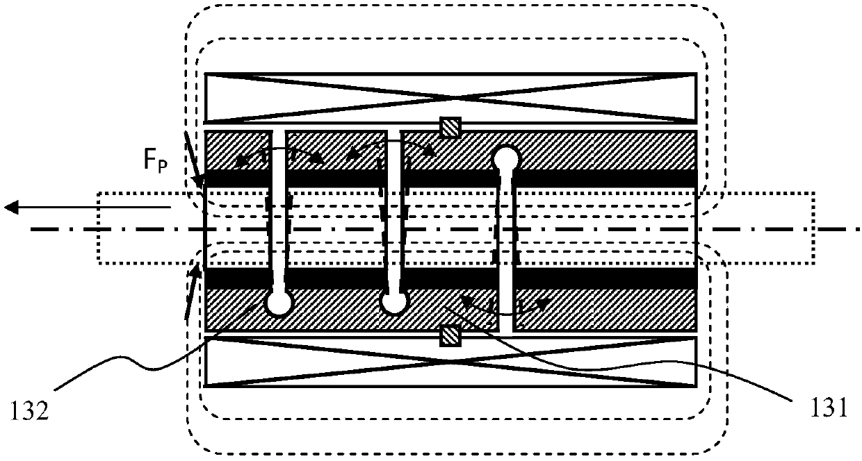
[0107] The displacement manipulation unit device provided in this embodiment includes a plurality of deformation actuators 100 described in Embodiment 1, and a plurality of deformation actuators 100 are installed in the same housing, but each deformation actuator 100 All are equipped with an independent driving electromagnet 210. The plurality of deformation actuators 100 include a first motion actuator 141 and a second motion actuator 142, and the first motion actuator 141 and the second motion actuator 142 are in the corresponding drive electromagnet 210. When energized alone, the direction in which it moves along the guide rail 301 or the direction in which the moving rod 302 is driven can change accordingly. Such as Figure 4 As shown, when the drive electromagnet 210 corresponding to the first movement actuator 141 is energized, the drive movement rod 302 moves to the right; Figure 5 As shown, when the driving electromagnet 210 corresponding to the second moving direct...
Embodiment 3
[0109] This embodiment is a modification of the structure provided in Embodiment 1, such as Figure 6As shown, the plurality of deformation actuators 100 include a first clamp actuator 151, a telescopic actuator 152 and a second clamp actuator 153, the first clamp actuator 151, the telescopic actuator 152 and the second clamp actuator 153 are sequentially connected. The first clamping actuator 151 , the telescoping actuator 152 and the second clamping actuator 153 are successively installed in the same shell. Wherein, the telescopic actuator 152 is axially fixed on the casing through the limiting block 311 , and the telescopic actuator 152 is provided with a plurality of driving slots 122 , and the plurality of driving slots 122 constitute one or more of the aforementioned driving groups 123 . The first clamp actuator 151 and the second clamp actuator 153 are respectively provided with one or more clamp grooves 121, along the circumferential direction of the deformation actua...
PUM
 Abstract
Description
Claims
Application Information