

Knife holder for microtome knives and microtome
a microtome knife and holder technology, applied in the field of holder, can solve the problems of affecting the operation of the microtom
- Summary
- Abstract
- Description
- Claims
- Application Information
AI Technical Summary
Benefits of technology
Problems solved by technology
Method used
Image

Examples
Embodiment Construction
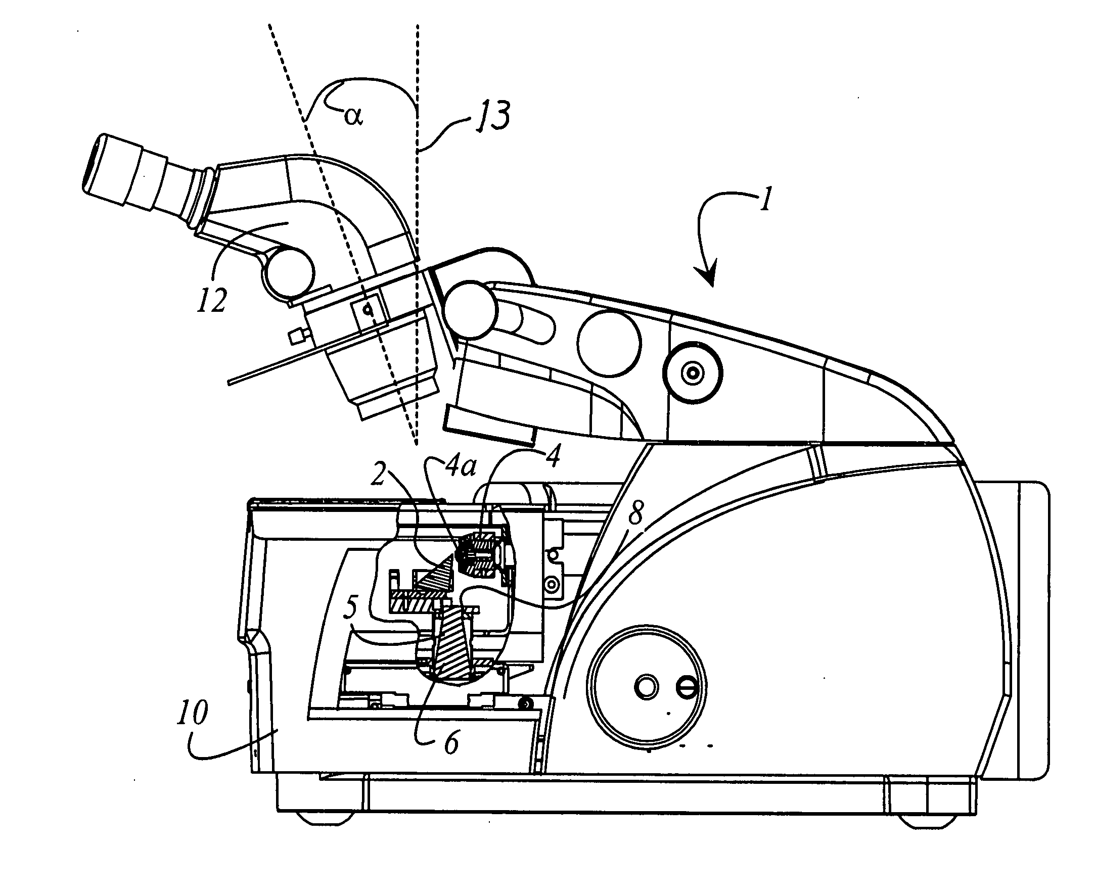
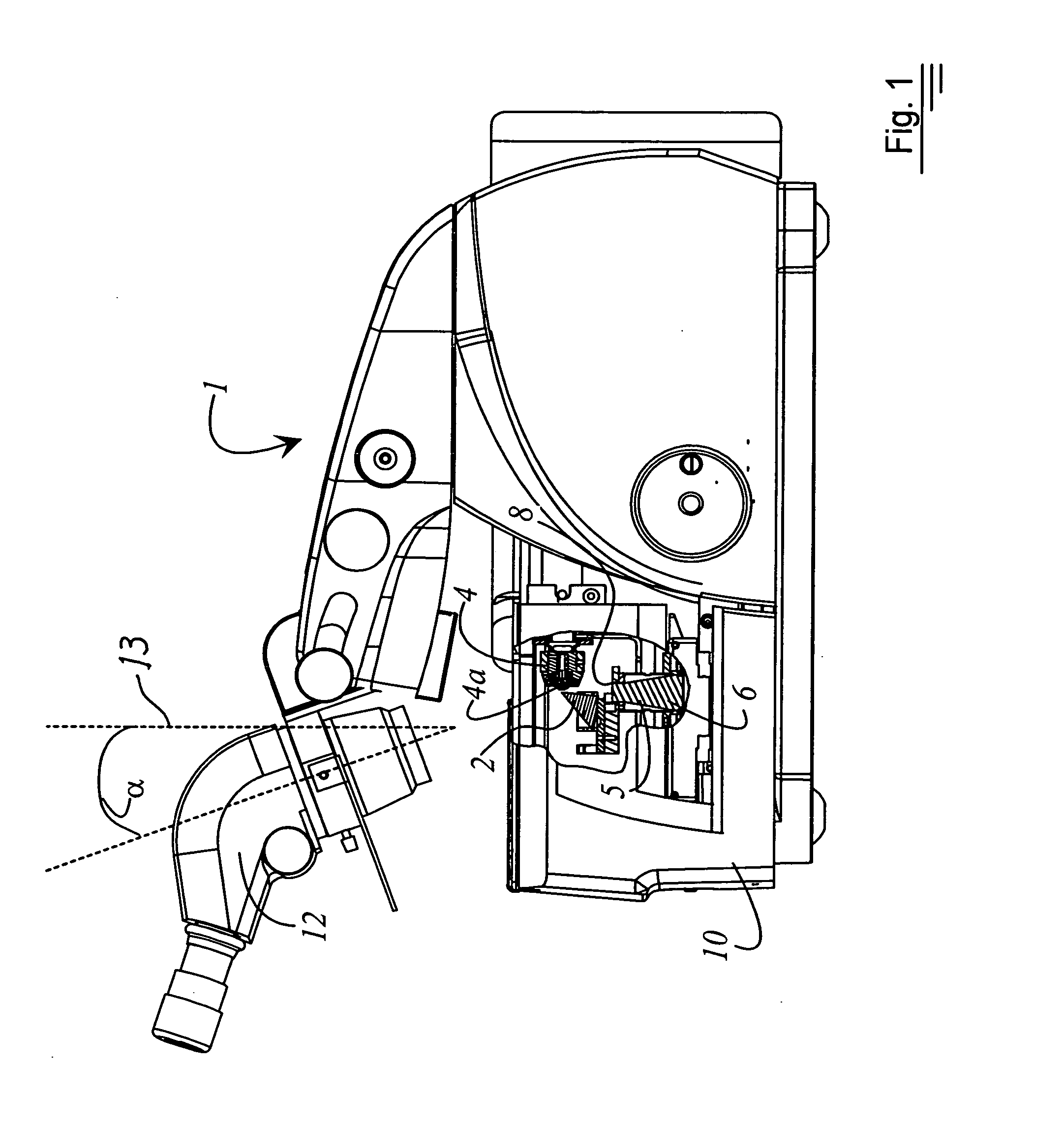
[0020]FIG. 1 is a side view of a microtome or ultramicrotome 1 having a cooling chamber 10. Parts of cooling chamber 10 are omitted in order to elucidate the association between at least one knife 2 and sample holder 4. The at least one knife 2 is inserted into a knife holder 5. Knife holder 5 is arranged with respect to a base-mounted illumination system 6 in such a way that exit opening 8 of base-mounted illumination system 6 is positioned below knife 2 that is currently in the working position. The working position is defined by the fact that knife 2 is positioned opposite sample holder 4. In the working position, thin sections of a sample 4a that is clamped in sample holder 4 can be produced with the knife.
[0021] Microtome 1 is provided with a stereomicroscope 12 that is mounted at a fixed angle a with respect to perpendicular 13. This configuration results in optimum contrast during alignment of knife 2 with respect to the surface of sample 4a that is to be cut. The provision ...
PUM
| Property | Measurement | Unit |
|---|---|---|
| angle | aaaaa | aaaaa |
| relief angle | aaaaa | aaaaa |
| temperature | aaaaa | aaaaa |
Abstract
Description
Claims
Application Information