
Knife holder for microtome knives and microtome

a microtome knife and holder technology, applied in the field of holder, can solve the problems of affecting the operation of the microtom

Active Publication Date: 2011-08-23
LEICA MICROSYSTEMS GMBH
View PDF13 Cites 7 Cited by
  • Summary
  • Abstract
  • Description
  • Claims
  • Application Information

AI Technical Summary

Benefits of technology

The present invention relates to a knife holder for a microtome, which allows for easy and fast replacement of knives without a long interruption in the cutting process. The knife holder carries at least two knives, each with a cutting edge, and is pivotably arranged about a shaft that is perpendicular to the cutting edges. The microtome also includes a cooling chamber and a sample holder opposite the knife holder. The knife holder can be easily removed from the cooling chamber without damaging the sample or sample holder. The technical effects of this invention include improved efficiency and accuracy in sample cutting and processing.

Problems solved by technology

This additional displacement capability has, however, the disadvantage that operator errors occur.
The knife holder is often displaced along with the illumination system for a knife change, thus disadvantageously modifying the illumination geometry.
When a cooling chamber is used, operation of the microtome is interrupted during replacement of the knife, since the temperature equilibrium (or “climate”) inside the cooling chamber is disturbed by the introduction of the new knife.
This so-called presetting operation also requires time, and care must be taken that neither the knife nor the specimen is damaged in the process.

Method used


Image

  • Knife holder for microtome knives and microtome
  • Knife holder for microtome knives and microtome
  • Knife holder for microtome knives and microtome

Examples


Embodiment Construction

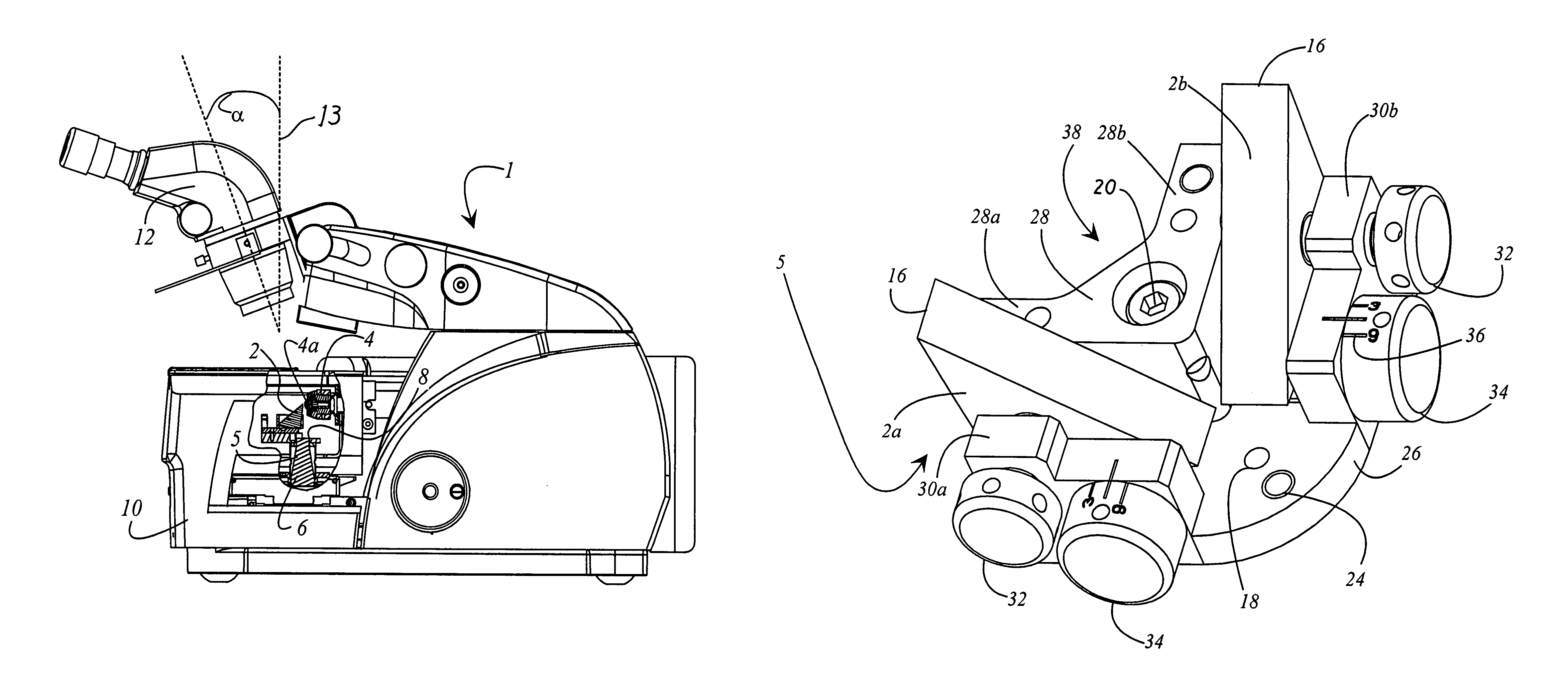
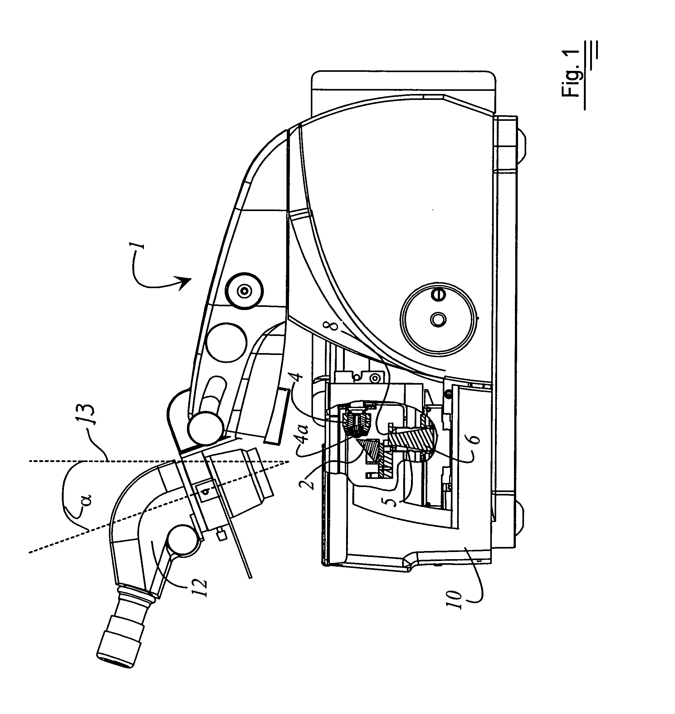
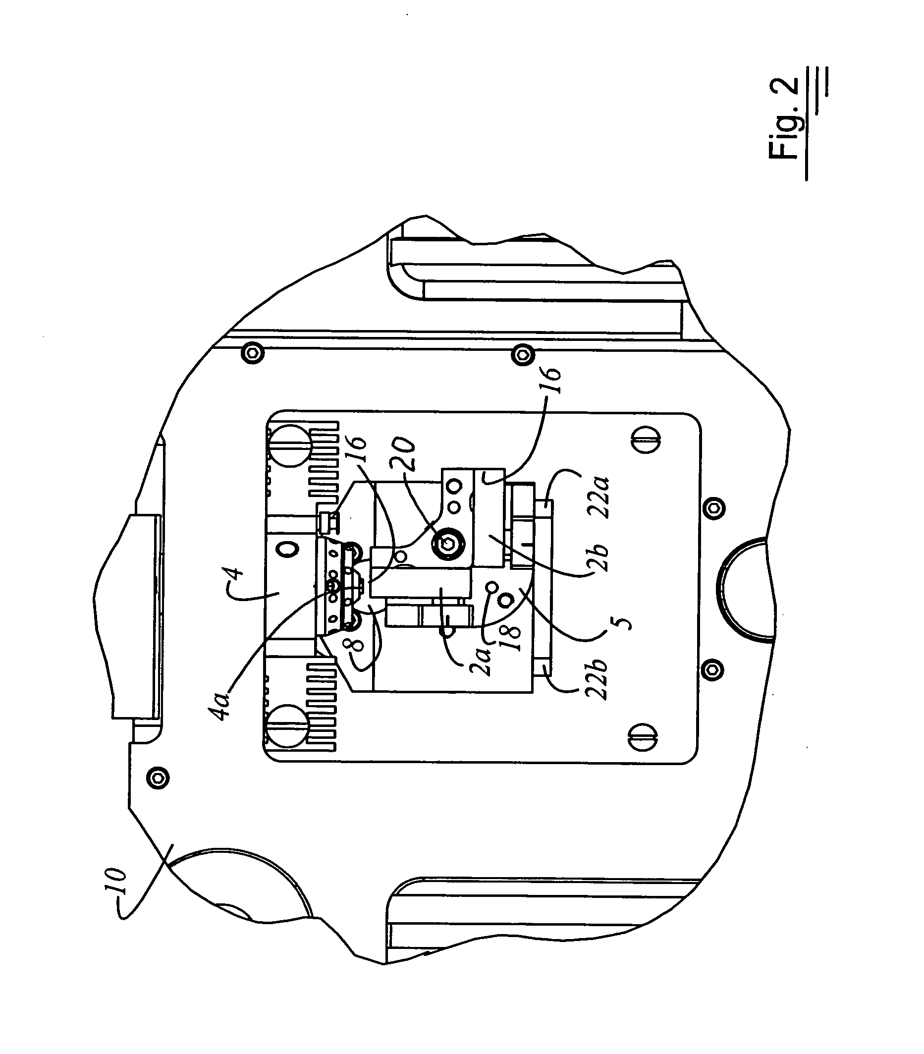
[0020]FIG. 1 is a side view of a microtome or ultramicrotome 1 having a cooling chamber 10. Parts of cooling chamber 10 are omitted in order to elucidate the association between at least one knife 2 and sample holder 4. The at least one knife 2 is inserted into a knife holder 5. Knife holder 5 is arranged with respect to a base-mounted illumination system 6 in such a way that exit opening 8 of base-mounted illumination system 6 is positioned below knife 2 that is currently in the working position. The working position is defined by the fact that knife 2 is positioned opposite sample holder 4. In the working position, thin sections of a sample 4a that is clamped in sample holder 4 can be produced with the knife.

[0021]Microtome 1 is provided with a stereomicroscope 12 that is mounted at a fixed angle a with respect to perpendicular 13. This configuration results in optimum contrast during alignment of knife 2 with respect to the surface of sample 4a that is to be cut. The provision of...


PUM

PropertyMeasurementUnit
angleaaaaaaaaaa
relief angleaaaaaaaaaa
temperatureaaaaaaaaaa

Abstract

A knife holder (5) for a microtome for cutting samples (4a) is disclosed. The knife holder (5) encompasses several knives (2a, 2b) each of which defines a cutting edge (16). The knife holder (5) is arranged pivotably about a shaft (18); and the shaft (18) is arranged substantially perpendicularly to each cutting edge (16) of the knives (2a, 2b).

Description

CROSS REFERENCE TO RELATED APPLICATIONS[0001]This application claims priority of the German patent application 103 46 995.8 filed Oct. 7, 2003 which is incorporated by reference herein.FIELD OF THE INVENTION[0002]The invention concerns a knife holder. The invention concerns in particular a knife holder for microtome knives for cutting samples. Additionally the invention concerns a microtome with the inventive knife holder.BACKGROUND OF THE INVENTION[0003]Microtomes and ultramicrotomes are, as a rule, equipped with two knives. One knife serves to trim the sample, and the other knife serves to produce the thin sections. Microtomes and / or ultramicrotomes can also be provided with a cooling chamber. During operation of a microtome with a cooling chamber, two or three knives are usually present in the chamber. One is used for trimming, and the second for producing the ultrathin sections. When a new knife is introduced from outside into the cooling chamber, it is necessary to wait a few m...

Claims


Application Information

Patent Timeline
Patent Type & Authority Patents(United States)
IPC IPC(8): B23D19/00G01N1/06
CPCG01N1/06G01N2001/061Y10S83/955Y10T83/6492Y10T83/9457Y10T83/6515Y10T83/828
Inventor LANG, ANTONLIHL, REINHARDWURZINGER, PAULHALLADY, ANDREAS
Owner LEICA MICROSYSTEMS GMBH
Learn More