Hydraulic flat cylinder, hydraulic lifting cushion and use thereof, and method for aligning a generator

a flat hydraulic cylinder and flat hydraulic technology, applied in the field can solve the problems of inconvenient use, leakage, and limited application of flat hydraulic cylinders, and achieve the effect of simple and precise fashion

Inactive Publication Date: 2017-02-16
WOBBEN PROPERTIES GMBH
View PDF6 Cites 1 Cited by
  • Summary
  • Abstract
  • Description
  • Claims
  • Application Information

AI Technical Summary

Benefits of technology

[0030]In a further aspect the invention concerns a method of orientating the relative position of a rotor with respect to a stator of a generator, in particular a (slowly rotating) synchronous generator, wherein there is an air gap between the rotor and the stator. The method according as explained hereinbefore provides an improved possible way of orienting the rotor and the stator relative to each other in a simple and precise fashion.

Problems solved by technology

Flat hydraulic cylinders generally function satisfactorily in the context of their areas of use, but they have some technical limitations.
A further serious disadvantage with the known flat hydraulic cylinders is the problem that, due to the principle involved, sealing means must be provided between the relatively movable parts of the piston and the main body, the sealing means preventing hydraulic fluid from issuing from the working chamber.
In the event of exceeding certain pressures or changes in the fluid composition however due to the principle involved leaks occur.
Those limitations mean that flat hydraulic cylinders are not suitable for all purposes of use.

Method used


Image

  • Hydraulic flat cylinder, hydraulic lifting cushion and use thereof, and method for aligning a generator
  • Hydraulic flat cylinder, hydraulic lifting cushion and use thereof, and method for aligning a generator
  • Hydraulic flat cylinder, hydraulic lifting cushion and use thereof, and method for aligning a generator

Examples


Embodiment Construction

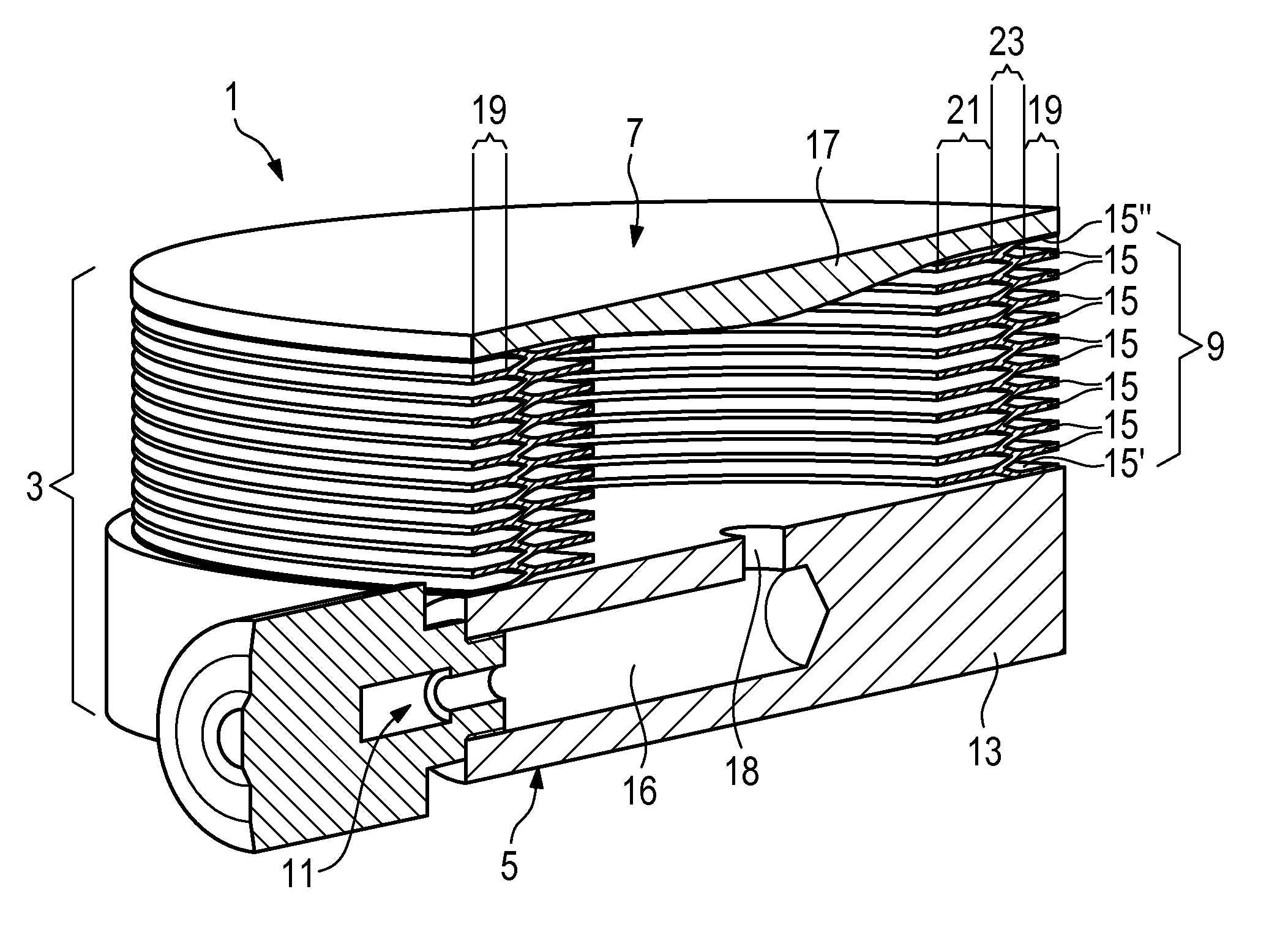
[0040]FIG. 1 shows a diagrammatic perspective view in section of a flat hydraulic cylinder 1. The flat hydraulic cylinder 1 has a housing 3. At its underside the housing 3 has a first force transmission surface 5 while at its opposite top side it has a second force transmission surface 7. The force transmission surface 5 and the force transmission surface 7 are connected by means of a housing wall 9 and are arranged variably in their spacing relative to each other.

[0041]A hydraulic connection 11 is provided for the inlet and outlet of hydraulic fluid into and out of the interior of the housing 3. The main body 13 has a blind hole 16 and a through bore 18 which provide access to the interior of the housing 3 for the hydraulic fluid.

[0042]In the flat hydraulic cylinder 1 in FIG. 1 the housing wall 9 is of a bellows-like configuration. It has a plurality of annular plates 15 stacked one upon the other. Of those plates a first plate 15′ is fixed to the main body 13, a last plate 15″ is ...


PUM


Abstract

A flat hydraulic cylinder comprising a housing which has a first force transmission surface, a second force transmission surface and a housing wall, wherein the second force transmission surface is arranged variably in spacing relative to the first force transmission surface, and a hydraulic connection for the inlet and outlet of hydraulic fluid into and out of the housing.
A hydraulic lift cushion which is in the form of a flat body and is dimensioned for introduction into an air gap between a rotor and a stator. According to the invention disclosure it is proposed that in those items of equipment the housing wall and the first and second force transmission surfaces constitute a one-piece pressure cushion.

Description

BACKGROUND[0001]Technical Field[0002]The present invention in a first aspect concerns a flat hydraulic cylinder.[0003]Description of the Related Art[0004]Flat hydraulic cylinders generally function satisfactorily in the context of their areas of use, but they have some technical limitations. On the one hand the structural height, in particular in the lifting direction, is relatively great as, to guide the piston in the main body, a certain minimum height must be guaranteed, so that on the one hand a sufficient lift travel is produced and on the other hand no tilting of the body in the main body occurs. A further serious disadvantage with the known flat hydraulic cylinders is the problem that, due to the principle involved, sealing means must be provided between the relatively movable parts of the piston and the main body, the sealing means preventing hydraulic fluid from issuing from the working chamber. In the event of exceeding certain pressures or changes in the fluid composition...

Claims


Application Information

Patent Timeline
Patent Type & Authority Applications(United States)
IPC IPC(8): F15B15/10H02K15/16
CPCH02K15/16F15B15/10B66F3/35H02K7/1838
Inventor ROER, JOCHEN
Owner WOBBEN PROPERTIES GMBH
Why Eureka
Try Eureka