
Method and magnetic resonance tomography apparatus for spatially resolved measurement of the B1 field distribution

a magnetic resonance tomography and spatial resolution technology, applied in the direction of magnetic measurements, instruments, measurement devices, etc., can solve the problems of ensuring that the correct average target flip angle is set in the measurement, and falsifying the results of the reading

Active Publication Date: 2005-04-07
SIEMENS HEALTHCARE GMBH
View PDF5 Cites 30 Cited by
  • Summary
  • Abstract
  • Description
  • Claims
  • Application Information

AI Technical Summary

Benefits of technology

The present invention provides a method for high-speed spatially resolved measurement of the B1 field distribution or flip angle distribution in magnetic resonance imaging (MRI) using a double echo high frequency pulse sequence with a first excitation pulse and at least two refocusing pulses. The method involves emitting an excitation pulse with a specified form, such as a sinc function, and then using suitable gradient pulses for phase or frequency coding to measure the echo images. The resulting data matrix can be Fourier transformed to obtain a two-dimensional image of the echoes with k-1 pixels. This allows for a precise measurement of the B1 field distribution and an in vivo adjustment of the B1 field distribution during an MRI examination. The method can be integrated into the conventional controller of the MRI apparatus or can be implemented as a software module.

Problems solved by technology

Spatial fluctuations in the field strength of the exciting B1 field therefore result in undesired variations in the received magnetic resonance signal, which can falsify the results of the reading.
Since the transmitter adjustment is performed only for the central, average layer, this procedure however can only guarantee that a correct average target flip angle is set in a measurement.

Method used


Image

  • Method and magnetic resonance tomography apparatus for spatially resolved measurement of the B1 field distribution
  • Method and magnetic resonance tomography apparatus for spatially resolved measurement of the B1 field distribution
  • Method and magnetic resonance tomography apparatus for spatially resolved measurement of the B1 field distribution

Examples


Embodiment Construction

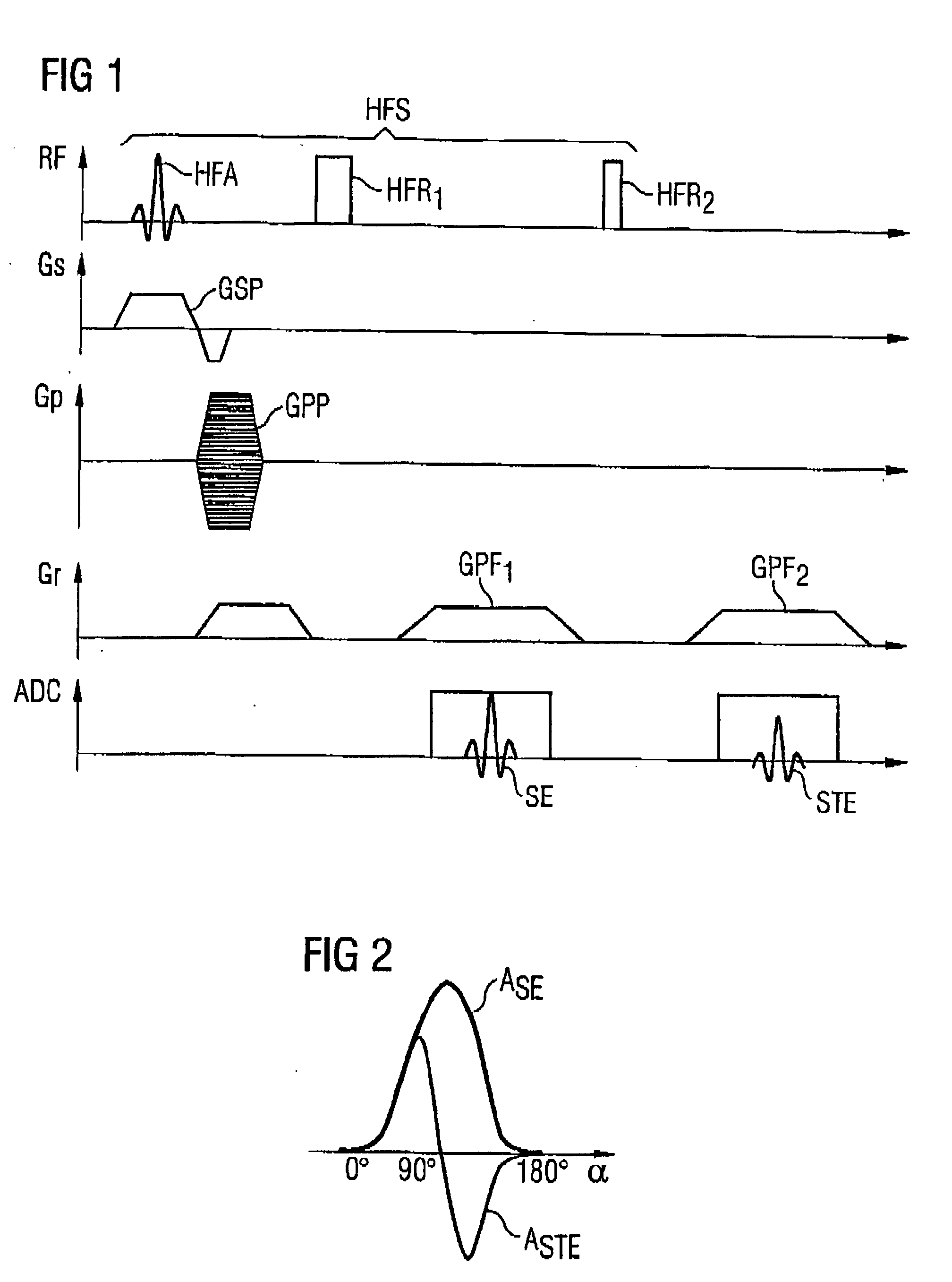
In the pulse sequence diagram shown in FIG. 1 the pulses emitted by the high frequency transmitting antenna and the various gradients switched appropriately in chronological dependency on the high frequency pulses are shown in conventional manner on parallel time axes.

The high frequency pulses emitted by the high frequency transmitter antenna are represented by the upper axis labeled with RF (radio-frequency). The Gs gradient represented below is the slice selection gradient, which is in the z-direction and effects a selection of a specified slice in which spins are excited. The phase encoding gradient Gp, which provides for phase encoding, is also shown. This phase encoding gradient is switched to different values very quickly during a measurement. The third gradient Gr is the read-out gradient or frequency-encoding gradient, which is activated to read out frequency encoded signals in a specified layer. In total, by appropriate switching of the phase encoding gradient Gp and the...


PUM


Abstract

In a method and magnetic resonance tomography apparatus for spatially resolved measurement of the magnetic high frequency field distribution in the apparatus, a double echo high frequency pulse sequence with a first excitation pulse following by at least two refocusing pulses are emitted for generation of a first echo and a following second echo. At least the excitation pulse is slice selective. In an excitation layer defined by the slice selective excitation pulse a first echo image and second echo image are spatially resolved by using suitable gradient pulses for phase or frequency encoding Using the relationships of the amplitudes of the first and second echo image in the various locations the flip angles representing the field strength at the relevant locations in the relevant slice are determined.

Description

BACKGROUND OF THE INVENTION 1. Field of the Invention The present invention relates to a method for spatially resolved measurement of the field distribution of high frequency pulses emitted from a high frequency antenna of a magnetic resonance scanning. In addition the invention relates to a magnetic resonance apparatus with a high frequency antenna and components for spatially resolved measurement of the field distribution of emitted high frequency pulses. 2. Description of the Prior Art Magnetic resonance imaging, also called magnetic resonance tomography, is a technique that is now widespread for acquiring images of the body interior of a living object to be examined. In order to acquire an image with this method, the body or the body part to be examined must first be exposed to a homogenous static basic magnetic field (usually characterized as a B0 field), which is generated by a basic field magnet of the magnetic resonance measuring instrument (scanner). During the data acq...

Claims


Application Information

Patent Timeline
Patent Type & Authority Applications(United States)
IPC IPC(8): G01R33/58
CPCG01R33/583
Inventor FEIWEIER, THORSTENHEUBES, PETER
Owner SIEMENS HEALTHCARE GMBH
Learn More