Adjustable spanner

Active Publication Date: 2005-04-14
HSIEN CHIH CHING
View PDF5 Cites 1 Cited by
  • Summary
  • Abstract
  • Description
  • Claims
  • Application Information

AI Technical Summary

Benefits of technology

[0006] The primary objective of the present invention is to provide an adjustable spanner, wherein the movable jaw is movable in the slideway of the main body smoothly and stably by the repulsive effect between the two magnetic members and the movable jaw or the main body, thereby facilitating the user operating the adjustable spanner.
[0007] Another objective of the present invention is to provide an adjustable spanner, wherein the two magnetic members are mounted in the main body or the movable jaw in a bonding or close fit manner, thereby preventing from detachment of the magnetic members during operation.
[0008] A further objective of the present invention is to provide an adjustable spanner, wherein each of the two magnetic members is made of a rigid material, so that the two magnetic members are mounted in the main body or the movable jaw easily and conveniently.
[0009] A further objective of the present invention is to provide an adjustable spanner, wherein each of the two magnetic members is flush with the neck portion of the movable jaw or the respective side wall of the slideway of the main body, so that each of the two magnetic members will not be worn during movement of the movable jaw.

Problems solved by technology

Thus, the movable jaw successively rubs the slideway of the fixed jaw during movement of the movable jaw, so that the movable jaw and the slideway of the fixed jaw are easily worn out due to friction, and the movable jaw cannot move smoothly.

Method used


Image

  • Adjustable spanner
  • Adjustable spanner
  • Adjustable spanner

Examples


Embodiment Construction

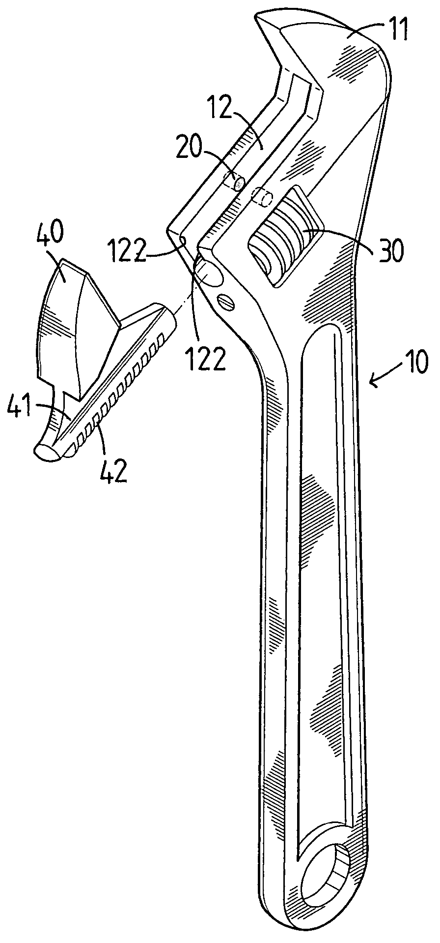
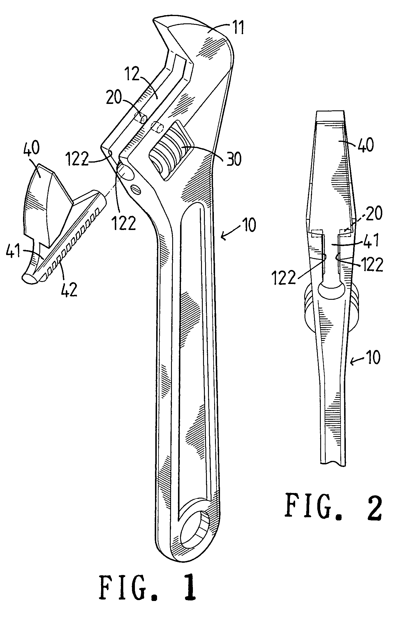
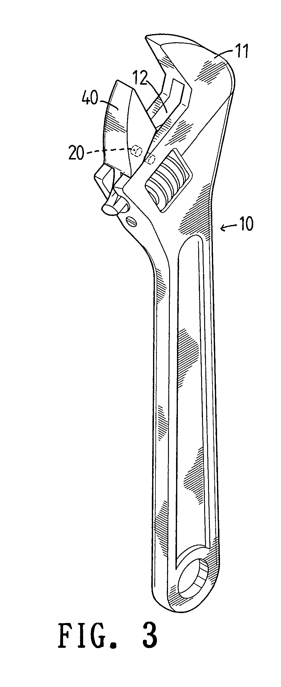
[0022] Referring to the drawings and initially to FIGS. 1-3, an adjustable spanner in accordance with the preferred embodiment of the present invention comprises a main body 10 having an end formed with a fixed jaw 11 and a transverse slideway 12 located adjacent to the fixed jaw 11, an adjustment screw 30 rotatably mounted in the main body 10, and a movable jaw 40 movably mounted on the main body 10 and having an end formed with a neck portion 41 having a bottom formed with a rack 42 slidably mounted in the slideway 12 of the main body 10 and engaged with the adjustment screw 30. Thus, the rack 42 is moved by rotation of the adjustment screw 30, so that the movable jaw 40 is moved relative to the fixed jaw 11.

[0023] The slideway 12 of the main body 10 has two opposite side walls 122. The neck portion 41 of the movable jaw 40 is slidably mounted in the slideway 12 of the main body 10 and located between the two opposite side walls 122 of the slideway 12 of the main body 10.

[0024] ...


PUM


Abstract

A adjustable spanner includes a main body formed with a fixed jaw and a slideway, an adjustment screw rotatably mounted in the main body, a movable jaw movably mounted on the main body and formed with a neck portion having a rack slidably mounted in the slideway and engaged with the adjustment screw, and two magnetic members mounted between the slideway and the movable jaw. Thus, the movable jaw is movable in the slideway smoothly by the repulsive effect between the magnetic members and the movable jaw or the main body, thereby facilitating the user operating the adjustable spanner.

Description

BACKGROUND OF THE INVENTION [0001] 1. Field of the Invention [0002] The present invention relates to an adjustable spanner, and more particularly to an adjustable spanner, wherein the movable jaw is movable in the slideway of the main body smoothly and stably, thereby facilitating the user operating the adjustable spanner. [0003] 2. Description of the Related Art [0004] A conventional adjustable spanner comprises a main body having a first end formed with a handle portion and a second end formed with a drive portion having a fixed jaw and a slideway, an adjustment screw rotatably mounted in the main body, and a movable jaw movably mounted on the drive portion and having a bottom formed with a rack slidably mounted in the slideway and engaged with the adjustment screw. Thus, the rack is moved by rotation of the adjustment screw, so that the movable jaw is moved relative to the fixed jaw. Thus, the user's one hand can hold the handle portion to rotate the drive portion so as to rotate...

Claims


Application Information

Patent Timeline
IPC IPC(8): B25B13/12B25B13/14
CPCB25B13/14B25B13/12
Inventor HSIEN, CHIH-CHING
Owner HSIEN CHIH CHING
Why Eureka
Try Eureka