Book block conveying device

Active Publication Date: 2021-06-17
HORIZON INTERNATIONAL INC
View PDF0 Cites 0 Cited by
  • Summary
  • Abstract
  • Description
  • Claims
  • Application Information

AI Technical Summary

Benefits of technology

[0040]According to the present invention, the book block conveying device comprises the first conveyor, and the second conveyor arranged between the first conveyor and the bookbinding apparatus. The first conveyor transports the book blocks placed on the transport surface on the one hand and can accumulate the book blocks on the transport surface on the other hand while being continuously operated at all times.
[0041]Moreover, the first stopper is arranged at the exit of the first conveyor, or between the first and second conveyors, or the entrance of the second conveyor, and the second stopper is arranged in the middle of the path of book block on the transport surface of the first conveyor. Each of the first and second stoppers is movable between the block position at which the stopper stops the book block and the retracted position at which the stopper allows passage of the book block.
[0042]Furthermore, the second conveyor and first, stopper is moved in synchronization with the motion of the bookbinding apparatus to take in

Problems solved by technology

Thereby it is possible to temporarily stop the bookbinding apparatus while continuously running the book block forming apparatus, and accordingly the decrease in production efficiency is inhibited.
However, according to this book block conveying device, if there is a great difference in the thickness between transported book blocks, the book block(s) sometimes collapse(s) when the accumulated book block(s) collide(s) with the subsequent book block, and thereby the book block cannot be supplied to the bookbinding apparatus.
Bes

Method used


Image

  • Book block conveying device
  • Book block conveying device
  • Book block conveying device

Examples


Example

[0050]A preferred embodiment of the present invention will be explained below with reference to accompanying drawings.

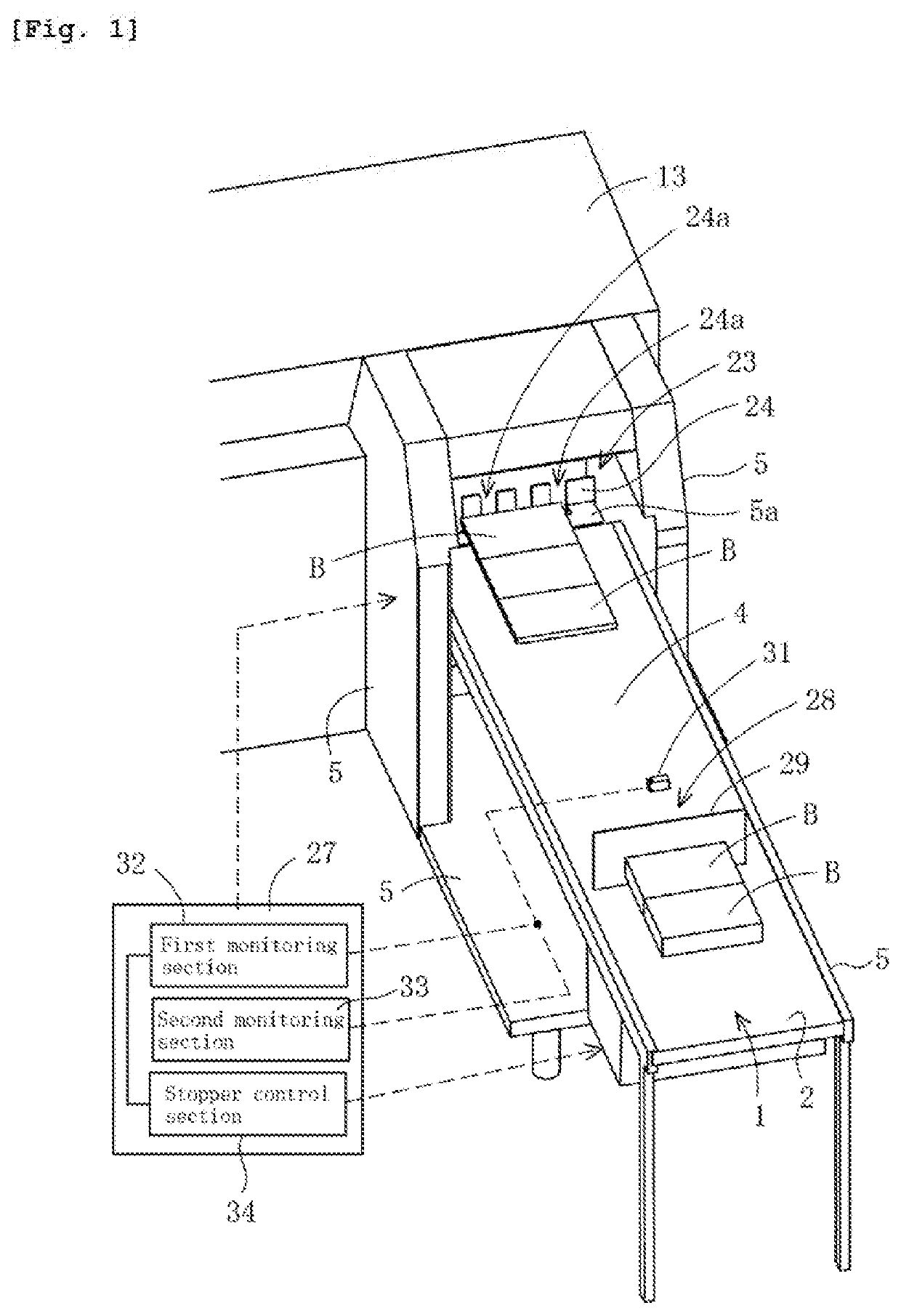
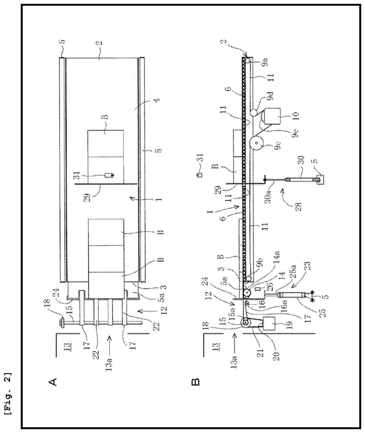
[0051]FIG. 1 is a perspective view of a book block, conveying device according to an embodiment of the present invention. FIG. 2(A) is a plan view of the book block conveying device shown in FIG. 1, and FIG. 2(B) is a front view of the book block conveying device shown in FIG. 1.

[0052]Referring to FIGS. 1 and 2, a book block conveying device comprises a first conveyor 1 having an entrance 2, an exit 3, and a transport surface 4 for a book block B extended from the entrance 2 and the exit 3.

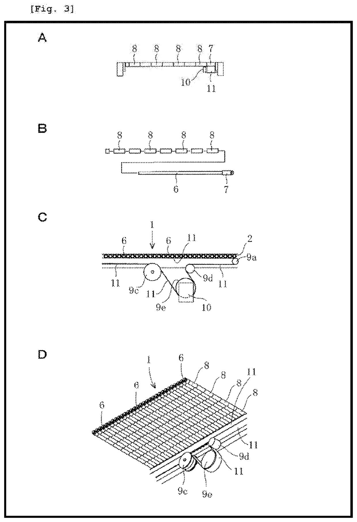
[0053]FIG. 3(A) is a side view illustrating a main part of the first conveyor 1 of the book block conveying device shown in FIG. 1, and FIG. 3(B) is a side view illustrating attachment of idle rollers to a rotating shaft of the first conveyor 1. FIG. 3(C) is a front, view illustrating a drive part of the first conveyor 1, and FIG. 3(D) is a perspective view of the drive part of the...


PUM


Abstract

The device includes a first conveyor 1 and a second conveyor 12. The first conveyor transports the book blocks B to the bookbinding apparatus and can accumulate the book blocks on a transport surface 4. A first stopper 23 is arranged at an entrance of the second conveyor and a second stopper 28 is arranged in the middle of a path of book block on the transport surface of the first conveyor. The first and second stoppers can take a block position and a retracted position. The second conveyor and the first stopper operate in synchronization with an operation of the bookbinding apparatus. The second stopper takes the block position when the number of book blocks accumulated on upstream side of the first stopper exceeds a predetermined limit value, or when a thickness difference between the book blocks transported side by side exceeds a predetermined reference value.

Description

TECHNICAL FIELD[0001]The present invention relates to a book block conveying device transporting book blocks one by one to a bookbinding apparatus so as to supply the book block to the bookbinding apparatus in synchronization with a motion of the bookbinding apparatus to take in the book block.BACKGROUND ART[0002]As a conventional bookbinding apparatus, for example, there is one disclosed in Patent Document 1.[0003]The bookbinding apparatus disclosed in Patent Document 1 comprises one or more clampers movable along a predetermined path while gripping a book block in a standing state, a series of processing units arranged along the path to carry out perfect bookbinding. The clamper includes a pair of clamp plates movable between an open position at which the pair of clampers receives the book block therebetween and a closed position at which the pair of clamp plates grips the book block therebetween.[0004]The bookbinding apparatus also comprises a book block supplying unit arranged a...

Claims


Application Information

Patent Timeline
IPC IPC(8): B42C19/08
CPCB42C19/08B42C19/04B65G47/295B65G47/31B65G43/08B65G43/10
Inventor KITAYAMA, SHINYAOKAMOTO, KOHEI
Owner HORIZON INTERNATIONAL INC
Why Eureka
Try Eureka