Lifting Device For An Overhead Projector Which Has A Constant Velocity During The Upward And Downward Movement

Inactive Publication Date: 2011-04-21
CHEN KUO HUA
View PDF19 Cites 2 Cited by
  • Summary
  • Abstract
  • Description
  • Claims
  • Application Information

AI Technical Summary

Benefits of technology

[0007]According to the primary advantage of the present invention, the drive unit is rotated normally in the positive direction to lift the overhead projector and is rotated at a slower speed in the reverse direction to lower the overhead projector so that the overhead projector is kept at a constant speed during the lifting and lowering process and is moved upward and downward smoothly and stably.
[0008]Further benefits and advantages of the present invention will become apparent after a careful reading of the detailed description with appropriate reference to the accompanying drawings.BRIEF DESCRIPTION OF THE SEVERAL VIEWS OF THE DRAWING(S)
[0009]FIG. 1 is a perspective view of a lifting device for an overhead projector in accordance with the preferred embodiment of the present invention.
[0010]FIG. 2 is a partially enlarged perspective view of the lifting device for an overhead projector as shown in FIG. 1.
[0011]FIG. 3 is a circuit diagram of the lifting device for an overhead projector as shown in FIG. 1.
[0012]FIG. 4 is a schematic operational view of the lifting device for an overhead projector as shown in FIG. 1 in use.

Problems solved by technology

Thus, the overhead projector is not kept at a constant speed during the lifting and lowering process so that the overhead projector is not moved smoothly and stably during the upward and downward movement.

Method used


Image

  • Lifting Device For An Overhead Projector Which Has A Constant Velocity During The Upward And Downward Movement
  • Lifting Device For An Overhead Projector Which Has A Constant Velocity During The Upward And Downward Movement
  • Lifting Device For An Overhead Projector Which Has A Constant Velocity During The Upward And Downward Movement

Examples


Embodiment Construction

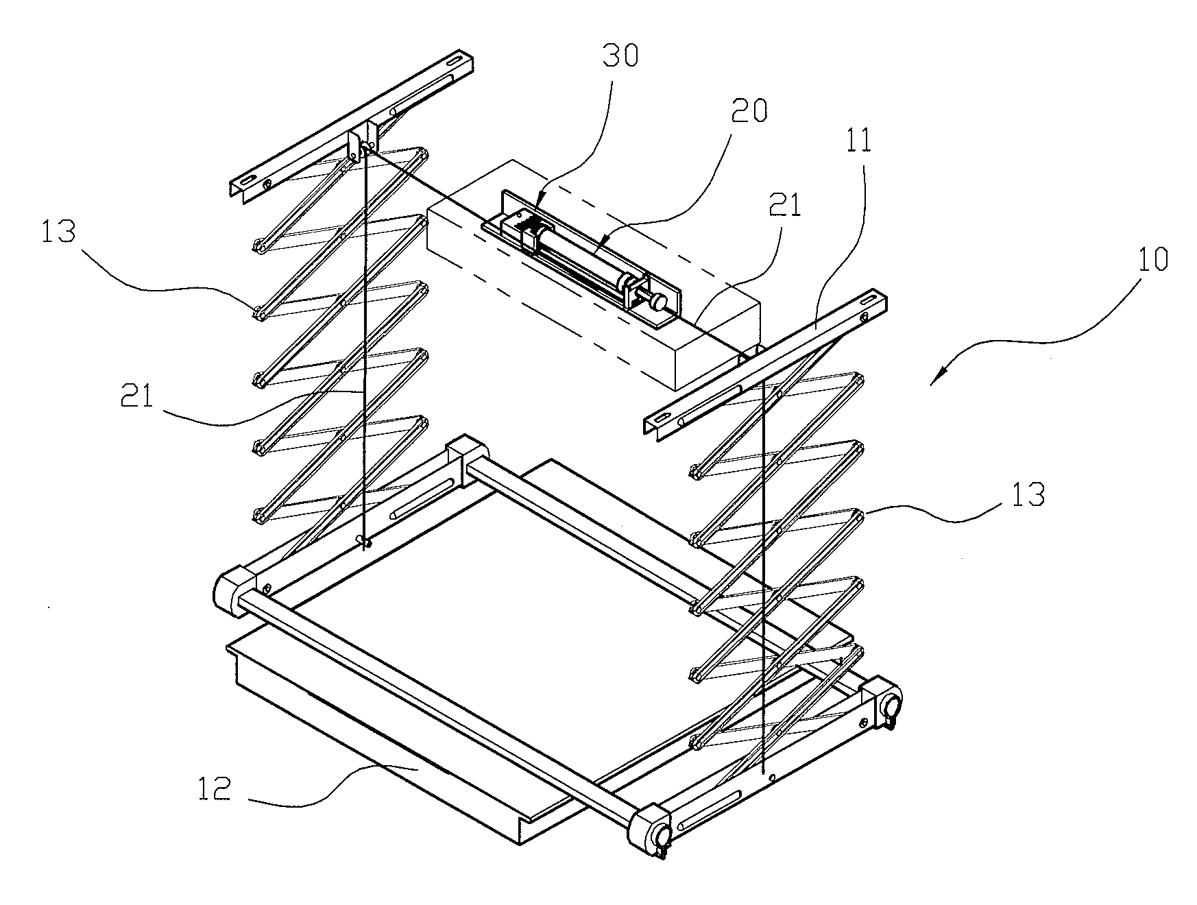
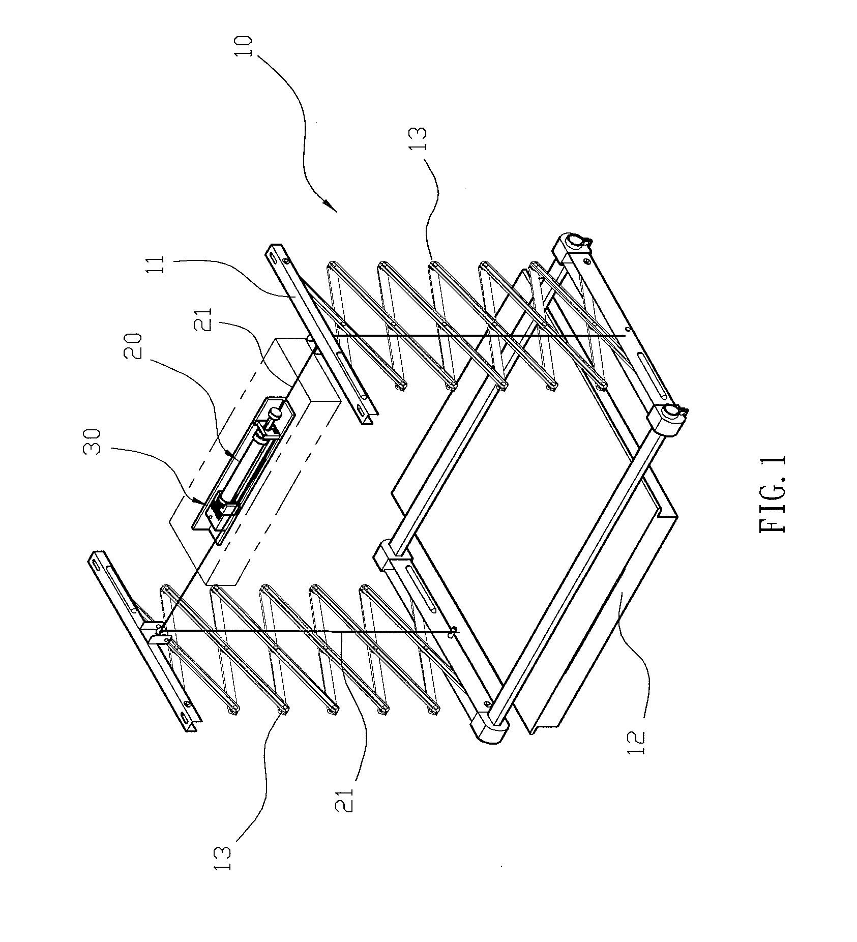
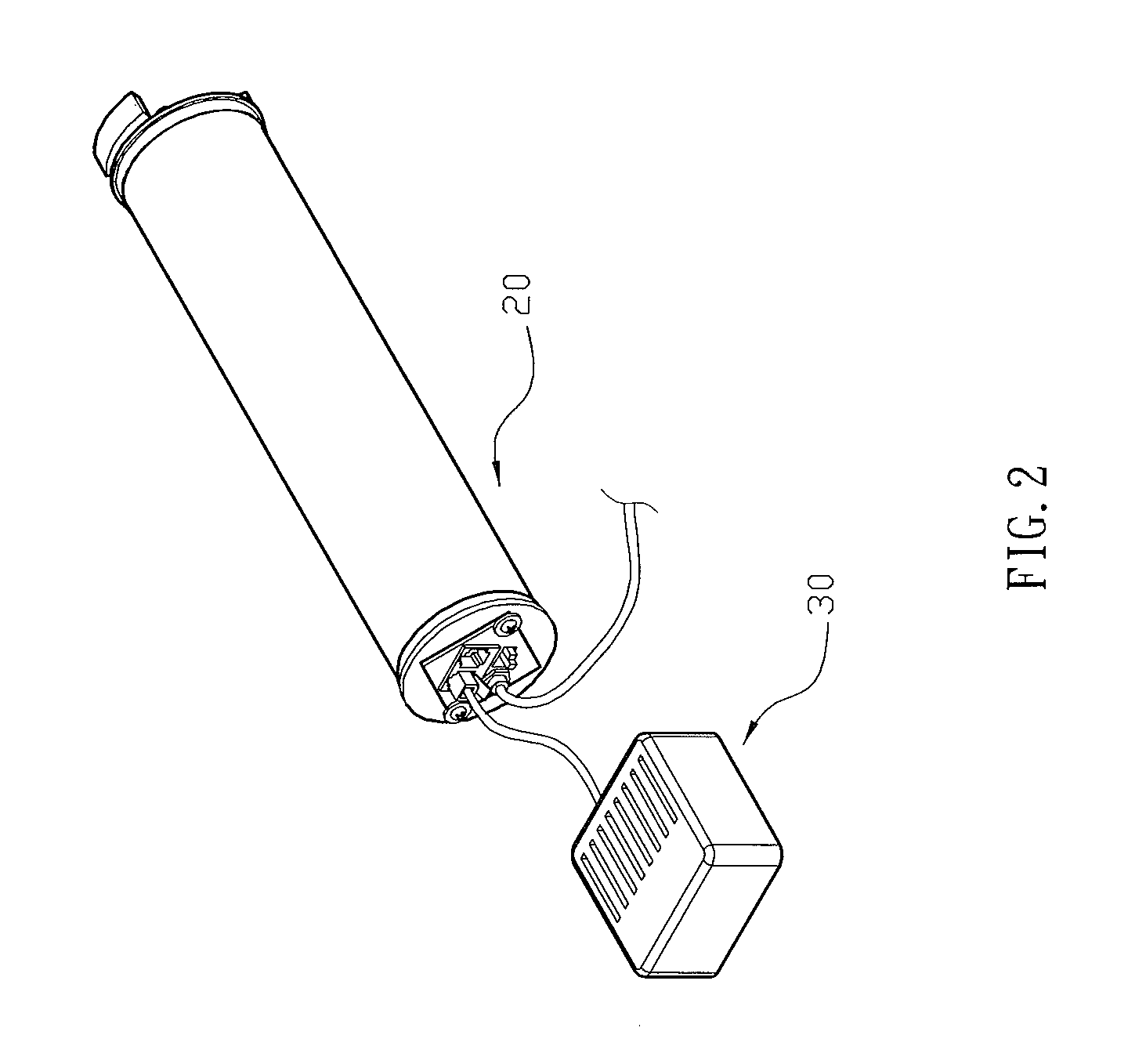
[0018]Referring to the drawings and initially to FIGS. 1-4, a lifting device for an overhead projector in accordance with the preferred embodiment of the present invention comprises a lifting unit 10, a drive unit 20 connected with the lifting unit 10 to control operation of the lifting unit 10, a braking unit 30 connected with the drive unit 20 to control operation of the drive unit 20, and a remote controller 35 connected with the braking unit 30 in a wireless manner to control operation of the braking unit 30.

[0019]The lifting unit 10 includes an upper frame 11, a lower frame 12 located under the upper frame 11 and two linking mechanisms 13 mounted between the upper frame 11 and the lower frame 12.

[0020]The drive unit 20 is mounted on the upper frame 11 of the lifting unit 10 and includes a lifting cord 21 which is extended through the upper frame 11 of the lifting unit 10 and connected with the lower frame 12 of the lifting unit 10 to move the lower frame 12 relative to the uppe...


PUM


Abstract

A lifting device includes a lifting unit, a drive unit connected with the lifting unit to control operation of the lifting unit, and a braking unit connected with the drive unit to control operation of the drive unit. The braking unit includes a microprocessor, a control circuit connected with the microprocessor, a changeover switch connected with the control circuit and the drive unit, and a control switch connected with the microprocessor and the changeover switch. Thus, the drive unit is rotated normally in the positive direction to lift the overhead projector and is rotated at a slower speed in the reverse direction to lower the overhead projector so that the overhead projector is kept at a constant speed during the lifting and lowering process and is moved upward and downward smoothly and stably.

Description

BACKGROUND OF THE INVENTION[0001]1. Field of the Invention[0002]The present invention relates to a lifting device and, more particularly, to a lifting device for an overhead projector.[0003]2. Description of the Related Art[0004]A conventional lifting device for an overhead projector comprises a lifting unit and a drive unit connected with the lifting unit to control operation of the lifting unit. The lifting unit has an upper end mounted on the ceiling and a lower end mounted on an overhead projector. Thus, the drive unit is operated to drive the lifting unit so as to lift or lower the overhead projector. However, when the drive unit is operated in the positive direction to lift the overhead projector, the overhead projector is moved upward at a slower speed due to its weight, and when the drive unit is operated in the reverse direction to lower the overhead projector, the overhead projector is moved downward at a higher speed due to its gravity. Thus, the overhead projector is not...

Claims


Application Information

Patent Timeline
IPC IPC(8): B66B1/32
CPCG03B21/54G03B21/132
Inventor CHEN, KUO-HUA
Owner CHEN KUO HUA
Why Eureka
Try Eureka