Rolling element retainer for a linear guideway

Active Publication Date: 2007-02-01
HIWIN TECH
View PDF3 Cites 6 Cited by
  • Summary
  • Abstract
  • Description
  • Claims
  • Application Information

AI Technical Summary

Benefits of technology

[0012] The primary objective of the present invention is to provide a rolling element retainer for a linear guideway having an improved rolling groove in which the rolling element with the retaining chain can move more smoothly and stably. The respective loading portions is provided at both ends thereof with an outward extensi

Problems solved by technology

However, the receiving groove of the whole circulating path is not a unitary structure but made up of several separate parts, consequently, a height difference will be caused at the connection

Method used


Image

  • Rolling element retainer for a linear guideway
  • Rolling element retainer for a linear guideway
  • Rolling element retainer for a linear guideway

Examples


Embodiment Construction

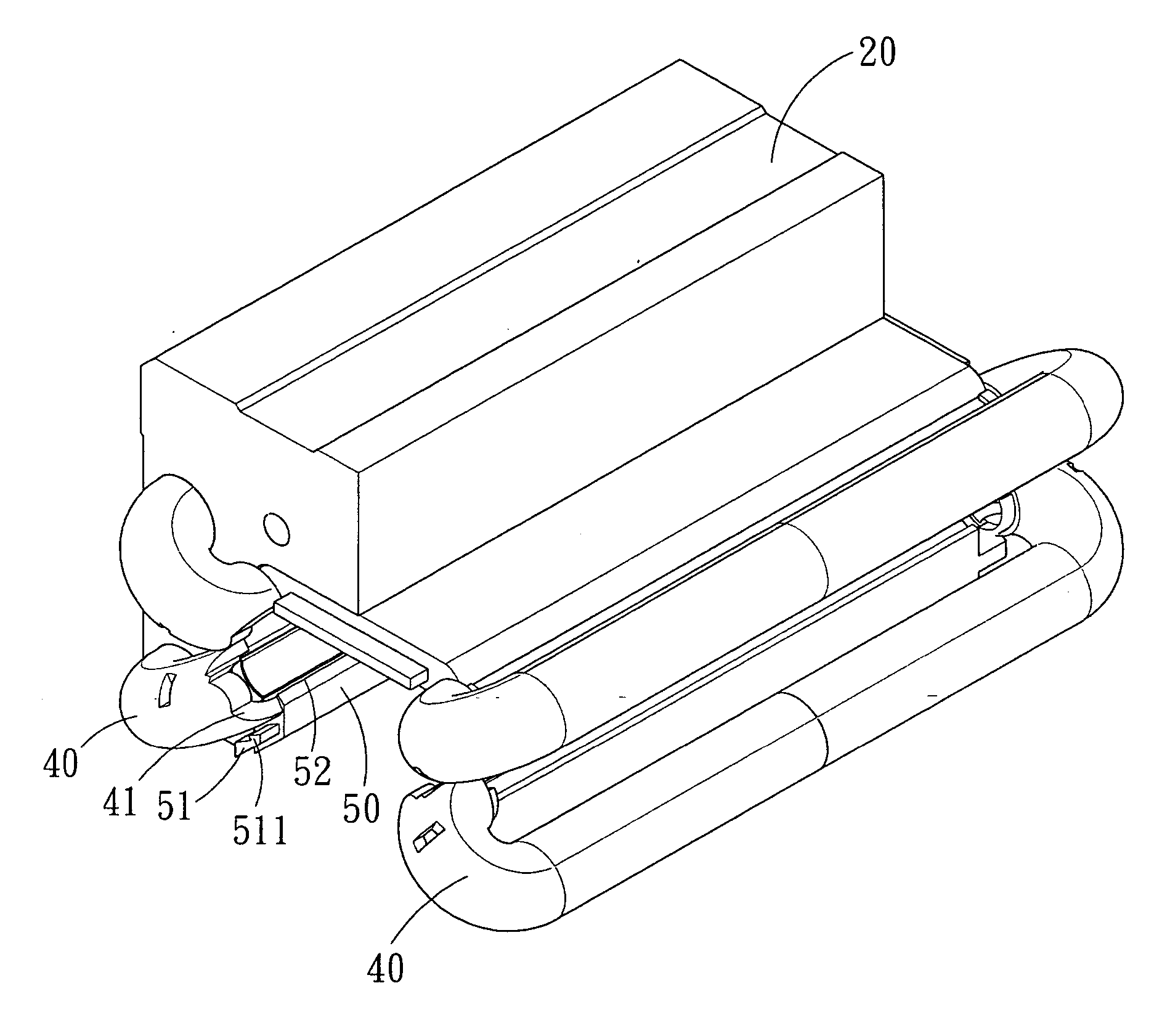
[0029] Referring to FIGS. 7-13, a type of the rolling element retainer for a linear guideway in accordance with the present invention comprises a slide block 20, a pair of end caps 30, a rolling passage 60, a plurality of direction-changing-area retainers 40 and a plurality of loaded-area retainers 50.

[0030] The end caps 30 are attached at either side of the slide block 20, and the direction-changing-area retainers 40 are disposed in an inner space 31 of the respective end caps 30.

[0031] The rolling passage 60 is arranged in the slide block 20.

[0032] The direction-changing-area retainers 40 each is provided at the end of the rolling groove 42 thereof with a guiding portion 41 that tapers outwardly toward its free end. The loaded-area retainers 50 are arranged in the slide block 20. The characteristics of this embodiment are explained as follows:

[0033] The end caps 30 are defined in the inner space 31 with a projection part 32 for mating with the guiding portion 41 and the rollin...


PUM


Abstract

A rolling element retainer for a linear guideway, wherein the rolling groove of the connective part of the rolling elements retaining chain is composed of a loaded area and a direction changing area. At either end of the loaded-area retainer is arranged an outward extension for mating with the direction-changing-area retainer. The outward extension extends in the direction of the rolling groove of the loaded-area retainer and abuts against a projection part of the end caps of the rolling element retainer. Therefore, not only the motion stability of the linear guideway is effectively improved, but also the rolling elements can move more smoothly.

Description

BACKGROUND OF THE INVENTION [0001] 1. Field of the Invention [0002] The present invention relates to a rolling element retainer, and more particularly to a rolling element retainer for a linear guideway. [0003] 2. Description of the Prior Art [0004] Linear guideway with rolling element retaining chain has been widely used on all types of precision sliding equipment, such as numerical control machine, automatic welding machine, transportation facilities, and the like. A general linear guideway is usually assembled in such a way that the rolling elements move endlessly along an annular rolling path, while a linear guideway with rolling element retaining chain must be provided in the whole circulating path with receiving groove for the passage of the linking portion of the rolling element retaining chain. However, the receiving groove of the whole circulating path is not a unitary structure but made up of several separate parts, consequently, a height difference will be caused at the c...

Claims


Application Information

Patent Timeline
IPC IPC(8): F16C29/06
CPCF16C29/06F16C33/3825F16C29/0642F16C29/0609F16C29/0647
Inventor HSIN-LIANG, CHENCHIN-PEI, WANG
Owner HIWIN TECH
Why Eureka
Try Eureka