Projection type video display

a video display and projection type technology, applied in the field of projection type video display, can solve the problems of unnecessary light entering the eyes of users, noise produced by offensive to the ear when a projector is employed, etc., to prevent unnecessary light from leaking out of the back of the light source, and reduce the sound of air suction and exhaust sound

Inactive Publication Date: 2005-04-14
SANYO ELECTRIC CO LTD
View PDF8 Cites 18 Cited by
  • Summary
  • Abstract
  • Description
  • Claims
  • Application Information

AI Technical Summary

Benefits of technology

[0010] In the above-mentioned configuration, the wind blower electrically moves the ionized air or the like to generate an air current. Accordingly, unlike blowing by the rotation of a fan, no rotation noise is produced, so that a sound of air suction and exhaust can be reduced up to almost soundless state. Even if the ozone is generated by the ionization, the ozone is removed by the ozone removal filter. The ozone removal filter is so arranged that its vents are inclined to the direction of light leaking out of the back of the light source and advancing toward the exhaust port or the suction port. Therefore, it is possible to prevent unnecessary light from leaking out of the exhaust port or the suction port.

Problems solved by technology

In a suction and exhaust mechanism using motor driving, however, noise is produced due to suction and exhaust sound by rotating sound of a motor and hissing sound of a fan, and the noise produced by the suction and exhaust sound is offensive to the ear when a projector is employed.
However, there is a disadvantage that light leaking out of a back of the light source 1 (unnecessary light) enters the eyes of a user after passing through the ozone decomposition catalyst filter 23 and the exhaust port.
Particularly, the projection type video display is employed in a room with a light darkened, so that unnecessary light is noticeable, thereby reducing the contrast of a projected video on a screen.
Further, the air current is also shut off, resulting in degradation in cooling capability.

Method used


Image

  • Projection type video display
  • Projection type video display
  • Projection type video display

Examples


Embodiment Construction

[0019] A projection type video display according to an embodiment of the present invention will be described on the basis of FIGS. 1 to 3.

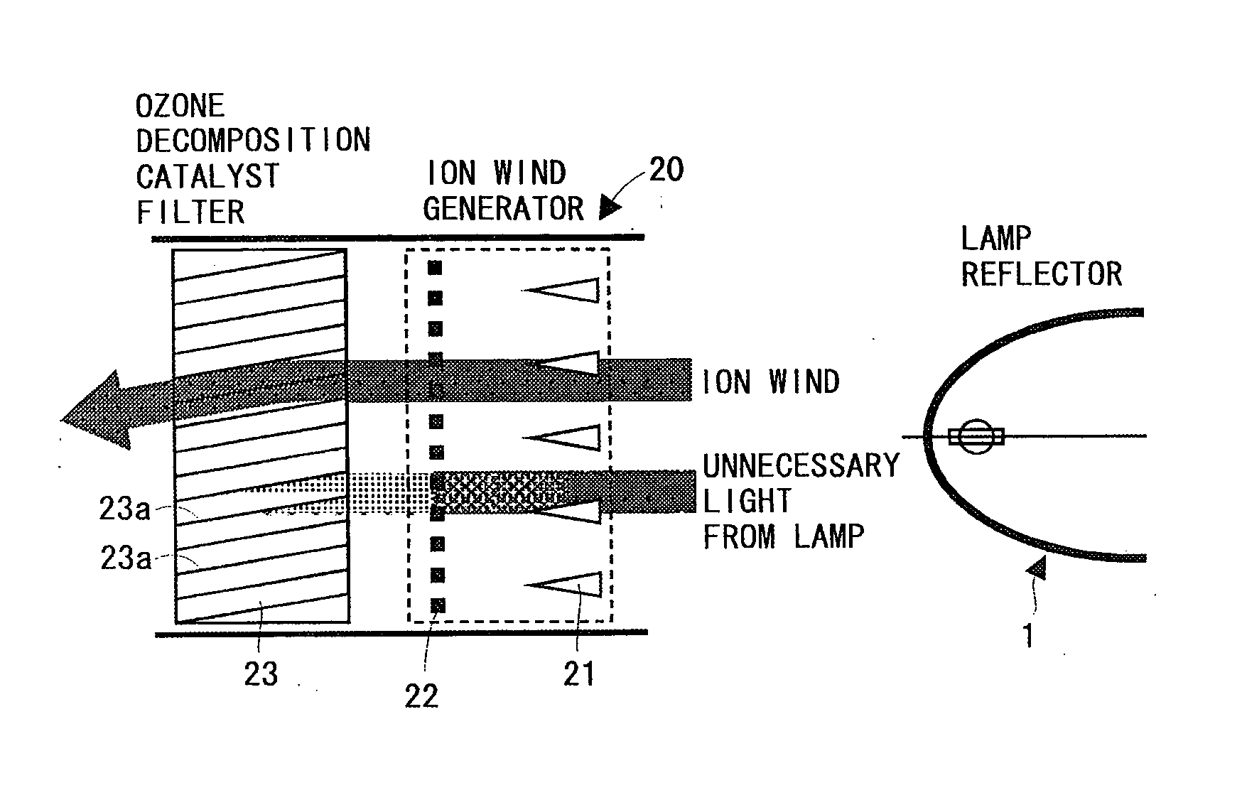
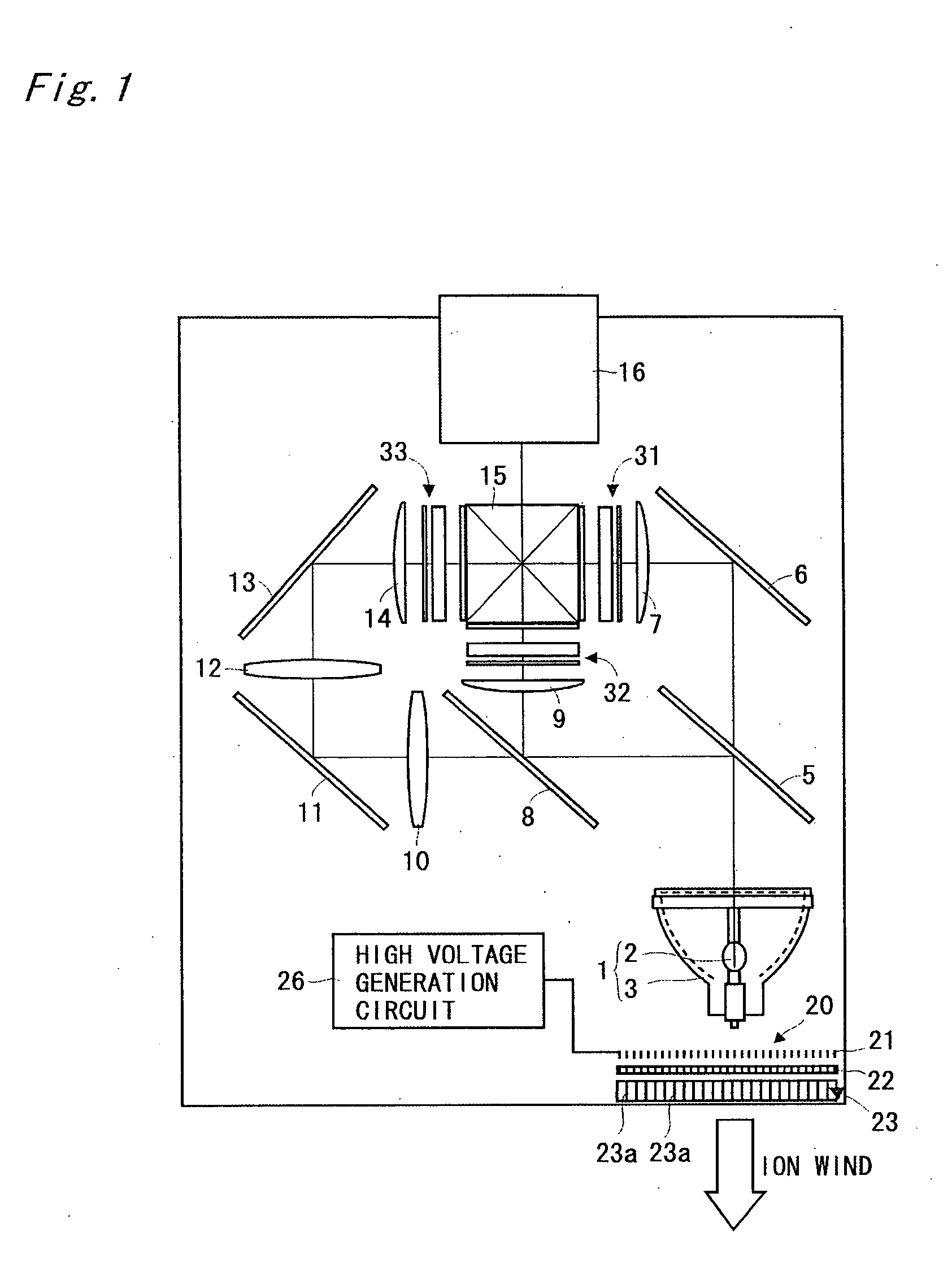
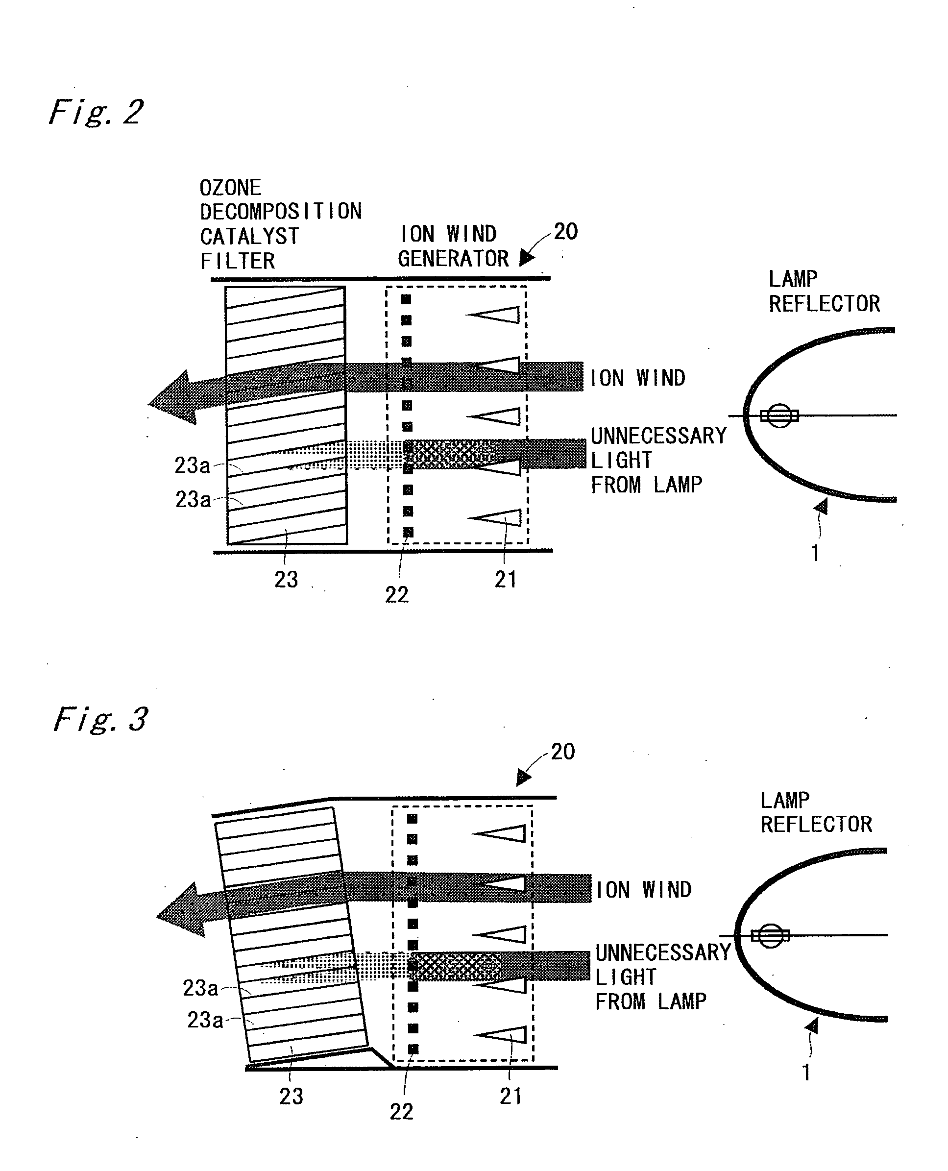
[0020]FIG. 1 is a diagram showing an optical system for a three-panel type color liquid crystal projector. A light emitter 2 in a light source 1 is composed of a ultra-high pressure mercury lamp, a metal halide lamp, a xenon lamp, or the like, and its irradiated light is emitted after being changed into parallel light by a parabolic reflector 3, for example.

[0021] A first dichroic mirror 5 transmits light in a red wavelength band, and reflects light in a cyan (green+blue) wavelength band. The light in the red wavelength band which has passed through the first dichroic mirror 5 is reflected from a mirror 6 so that its optical path is changed. The red light which is reflected from the mirror 6 is optically modulated by passing through a transmission type liquid crystal light valve for red light 31 through a condenser lens 7. On the other hand, the...


PUM

PropertyMeasurementUnit
luminanceaaaaaaaaaa
air currentaaaaaaaaaa
temperatureaaaaaaaaaa

Abstract

An ion wind generator is provided behind a light source. The ion wind generator 20 negatively-ionizes air by corona discharges using needle-shaped electrodes on the negative side, and draws the negatively-ionized air by a mesh electrode on the ground side to generate an air current. An exhaust port is provided with an ozone decomposition catalyst filter. A path axis for vent holes in the ozone decomposition catalyst filter is inclined to the direction of advancement (a direction toward the exhaust port) of unnecessary light from a lamp from the light source, and the unnecessary light from a lamp is shaded by the ozone decomposition catalyst filter.

Description

BACKGROUND OF THE INVENTION [0001] 1. Field of the Invention [0002] The present invention relates to a projection type video display such as a liquid crystal projector. [0003] 2. Disclosure of the Background Art [0004] A projection type video display is so configured that light emitted from a light source is modulated by a light valve such as a liquid crystal panel to be projected, so that it must comprise a high-luminance light source. Consequently, measures to prevent heat generated from the high-luminance light source itself and heat generated when light is absorbed in a light polarizing plate in the liquid crystal panel or various types of optical components are required. Conventionally, a projection type video display has a structure in which air is sucked and exhausted and heat is released from the video display by rotating a fan with a motor (see JP-A-2001-222065). SUMMARY OF THE INVENTION [0005] In a suction and exhaust mechanism using motor driving, however, noise is produc...

Claims


Application Information

Patent Timeline
Patent Type & Authority Applications(United States)
IPC IPC(8): G03B21/16G02F1/13G03B21/00G03B21/14H01T23/00H04N5/66H04N5/74H04N9/31
CPCH01T23/00H04N9/3197H04N9/3144H04N9/3141
Inventor IKEDA, TAKASHIISHII, KOJI
Owner SANYO ELECTRIC CO LTD
Why Eureka
Try Eureka