Projection device, projection system, and interface apparatus

a projection device and projection system technology, applied in the field of projection devices, projection systems, interface apparatus, can solve problems such as delay in processing, and achieve the effect of preventing unnecessary light from being projected and improving the contrast of a projected target imag

Active Publication Date: 2020-04-14
NEC CORP
View PDF10 Cites 0 Cited by
  • Summary
  • Abstract
  • Description
  • Claims
  • Application Information

AI Technical Summary

Benefits of technology

[0018]The present invention is able to provide a projection device capable of improving contrast of a projected target image by using a phase modulation type spatial modulation element, and preventing unnecessary light from being projected.

Problems solved by technology

Accordingly, an amount of calculation may become enormous and may cause delay in the processing when a projection environment is changed or a dynamic image is displayed.

Method used


Image

  • Projection device, projection system, and interface apparatus
  • Projection device, projection system, and interface apparatus
  • Projection device, projection system, and interface apparatus

Examples


first example embodiment

(Configuration)

[0053]First, a configuration of a projection device 1 according to a first example embodiment of the present invention will be described referring to drawings.

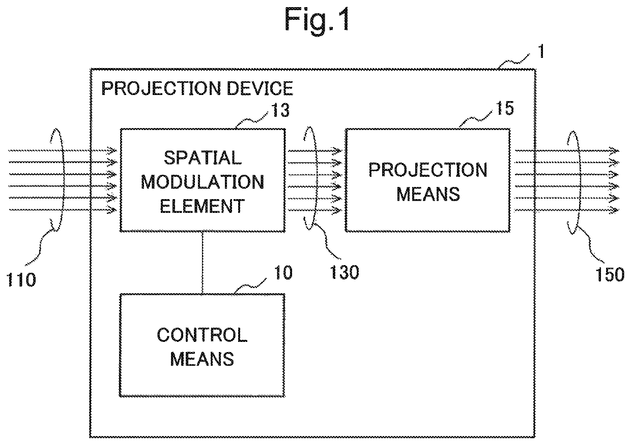
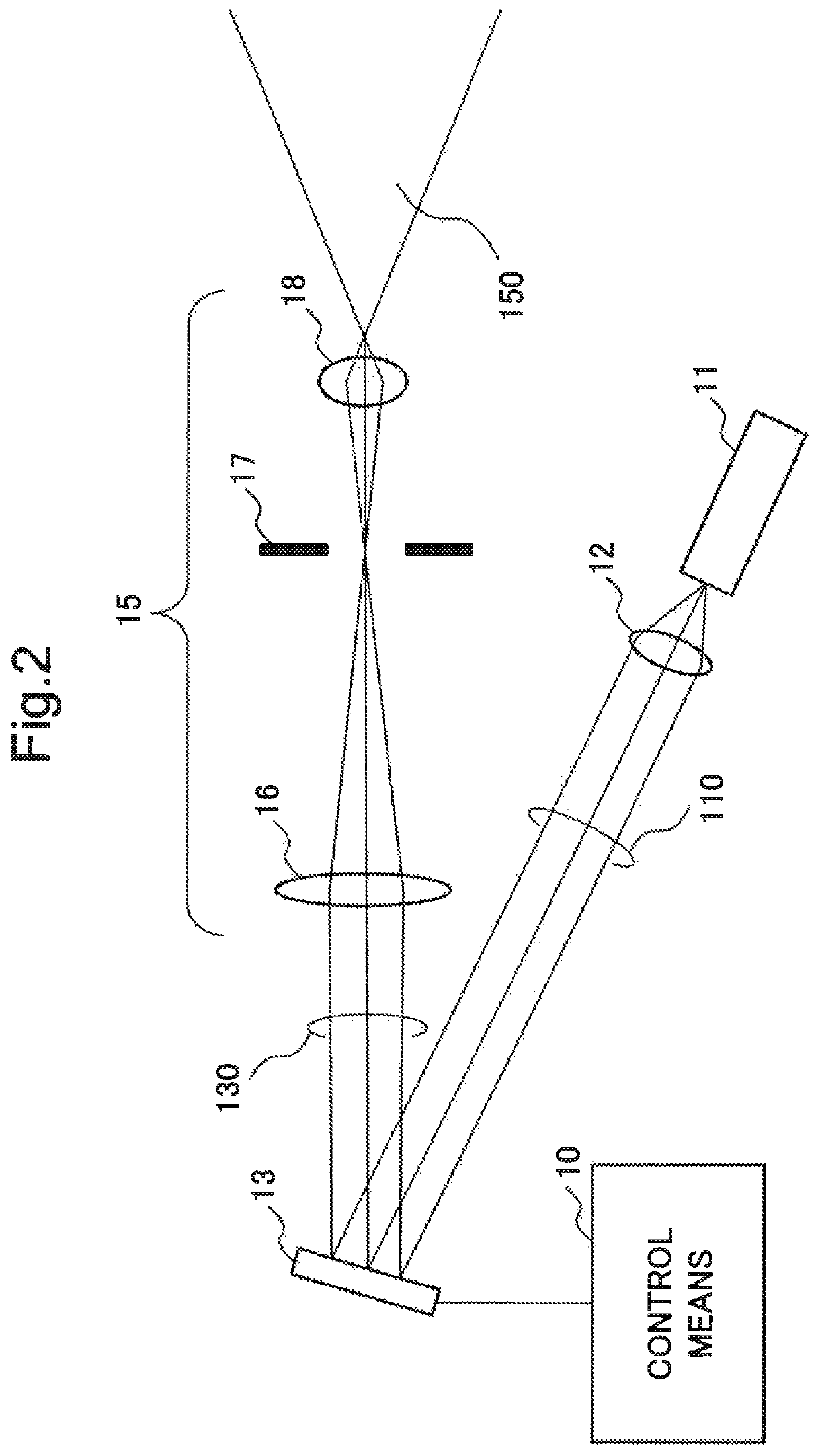
[0054]FIG. 1 is a block diagram illustrating a configuration of the projection device 1 according to the present example embodiment. As illustrated in FIG. 1, the projection device 1 according to the present example embodiment includes a control means 10, a spatial modulation element 13, and a projection means 15.

[0055]The control means 10 takes information (hereinafter referred to as target image information) related to a projected image (also referred to as a target image) as an input from an upper system such as a server. Based on the input target image information, the control means 10 generates a phase distribution for forming on a projection surface a light intensity distribution related to the target image (hereinafter referred to as a phase distribution of the target image). Furthermore, the control mean...

second example embodiment

[0120]Next, a second example embodiment according to the present invention will be described referring to drawings. The present example embodiment stores in a basic image storage unit 21 a phase distribution of a basic image in which sweep-out regions are set above and below a signal region. Note that a control device according to the present example embodiment has the same configuration as the control device 10 according to the first example embodiment, and therefore a drawing thereof is omitted.

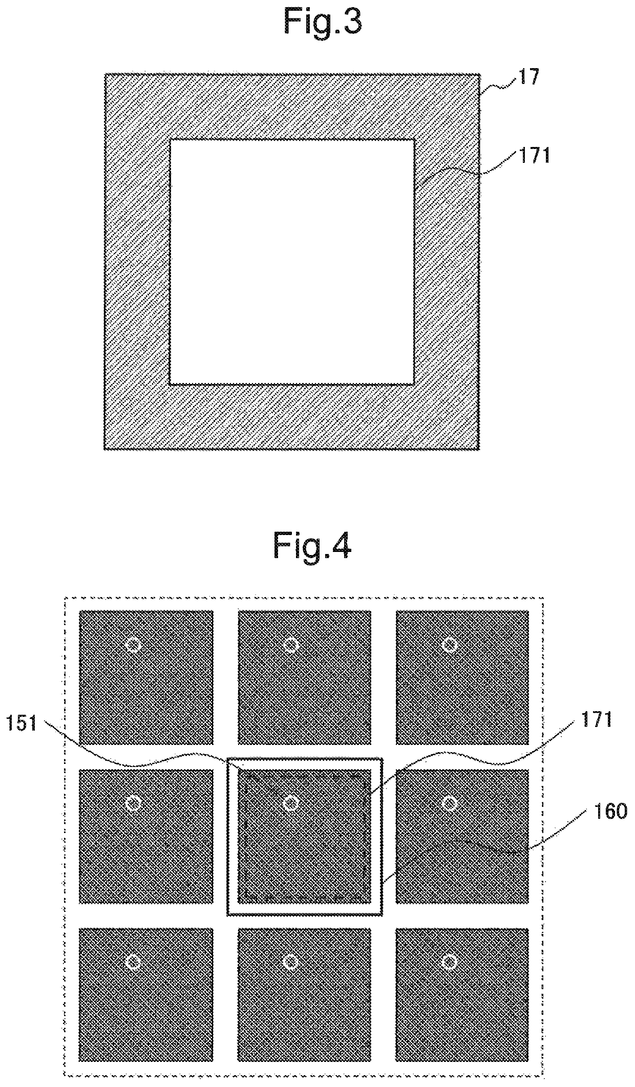
[0121]FIGS. 17 and 18 are examples of performing translation processing on a basic image in which sweep-out regions 163 are set above and below a signal region 164. Furthermore, as illustrated in FIG. 19, the present example embodiment uses an aperture 17-2 on which a rectangular opening 172 is formed. In order to avoid a spot of zeroth order light, the opening 172 on the aperture 17-2 is set with a small signal region being a high-contrast region. Accordingly, the opening 172 on the apertu...

third example embodiment

[0132]Next, a third example embodiment according to the present invention will be described referring to drawings. A projection device according to the present example embodiment includes an aperture 17-3 on which a circular opening 173 is formed in place of the aperture 17 on which the rectangle opening 171 is formed. The projection device according to the present example embodiment has the same configuration as the control device 10 according to the first example embodiment except for the aperture 17-3.

[0133]FIG. 22 illustrates the aperture 17-3 included in the control device according to the present example embodiment. The circular opening 173 is formed on the aperture 17-3.

[0134]FIG. 23 is a diagram extracting the inside of a zeroth-order region 160. Note that the example in FIG. 23 is an example of rotating a square basic figure (□) by 45 degrees and projecting the basic figure.

[0135]As modulated light 130 reflected by a display part on a spatial modulation element 13 passes th...


PUM


Abstract

A projection device is provided in order to improve contrast of a target image projected by using a phase modulation type spatial modulation element and also preventing unnecessary light from being projected. The projection device includes: a projection means that includes a light source, a spatial modulation element including a display part that displays a phase distribution of a target image and reflecting light from the light source, and an opening frame through which reflected light from the spatial modulation element passes; and a control means that causes the display part of the spatial modulation element to display a phase distribution generated by performing iterative Fourier transform processing by using an amplitude distribution set with a signal region in which a basic figure included in the target image is arranged and a sweep-out region for sweeping optical noise out of the signal region.

Description

[0001]This application is a National Stage Entry of PCT / JP2016 / 002931 filed on Jun. 17, 2016, which claims priority from Japanese Patent Application 2015-125298 filed on Jun. 23, 2015, the contents of all of which are incorporated herein by reference, in their entirety.TECHNICAL FIELD[0002]The present invention relates to a projection device including a phase modulation type spatial modulation element, a projection system, and an interface apparatus.BACKGROUND ART[0003]Development of an interface apparatus combining a projector with a camera has been under way in recent years. Such an interface apparatus provides an interactive operation by detecting, with a camera, a manipulation performed on an image projected from a projector. NPL 1 discloses an interface apparatus combining a projector with a camera.[0004]When a phase modulation type spatial modulation element is used in a projector in an interface apparatus, a phase distribution related to a displayed image is displayed on a di...

Claims


Application Information

Patent Timeline
Patent Type & Authority Patents(United States)
IPC IPC(8): G03B21/00H04N5/74G03H1/16G03H1/22G06F3/03G09G5/00G09G3/20H04N9/31G03H1/08G03B21/20
CPCG03H1/22G09G5/00H04N9/3179G03H1/2294G03B21/005G06F3/0304H04N5/74G09G3/20G03H1/16G03H1/2205G03H2225/32G09G2340/0492G09G2340/0464G03H2001/2218G03B21/2033G03H2001/0825
Inventor OKUMURA, FUJIO
Owner NEC CORP
Why Eureka
Try Eureka