
Light integration apparatus for use in a projection device

a technology of light integration apparatus and projection device, which is applied in the direction of projectors, optics, instruments, etc., can solve the problems of more light loss, complicated assembly of projection device, and conventional illumination structure, so as to prevent unnecessary light loss and improve the efficiency of utilizing light sources

Active Publication Date: 2012-08-28
DELTA ELECTRONICS INC
View PDF7 Cites 0 Cited by
  • Summary
  • Abstract
  • Description
  • Claims
  • Application Information

AI Technical Summary

Benefits of technology

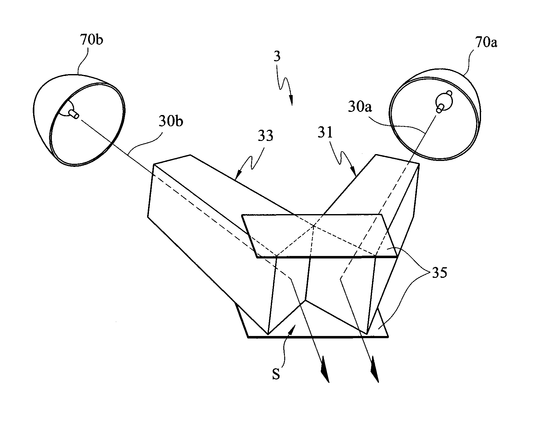
[0011]One objective of the present invention is to provide a light integration apparatus for use in a projection device, which is capable of integrating multiple light sources. By eliminating some integration rods disposed at the back end, the light integration apparatus of the present invention can prevent unnecessary light loss and improve the efficiency of utilizing light sources.
[0012]Another objective of the present invention is to provide a light integration apparatus for use in a projection device, which is capable of forming an uniform light source with a size suited to the DMD. Light emitted from different light sources is integrated to travel in a direction parallel to the symmetric axis by disposing two integration rods symmetrically with respect to the symmetric axis. In this way, it is easier to maintain and replace the components as well as maintain a simplified arrangement of the light source. In addition, the efficiency of heat dissipation is increased.

Problems solved by technology

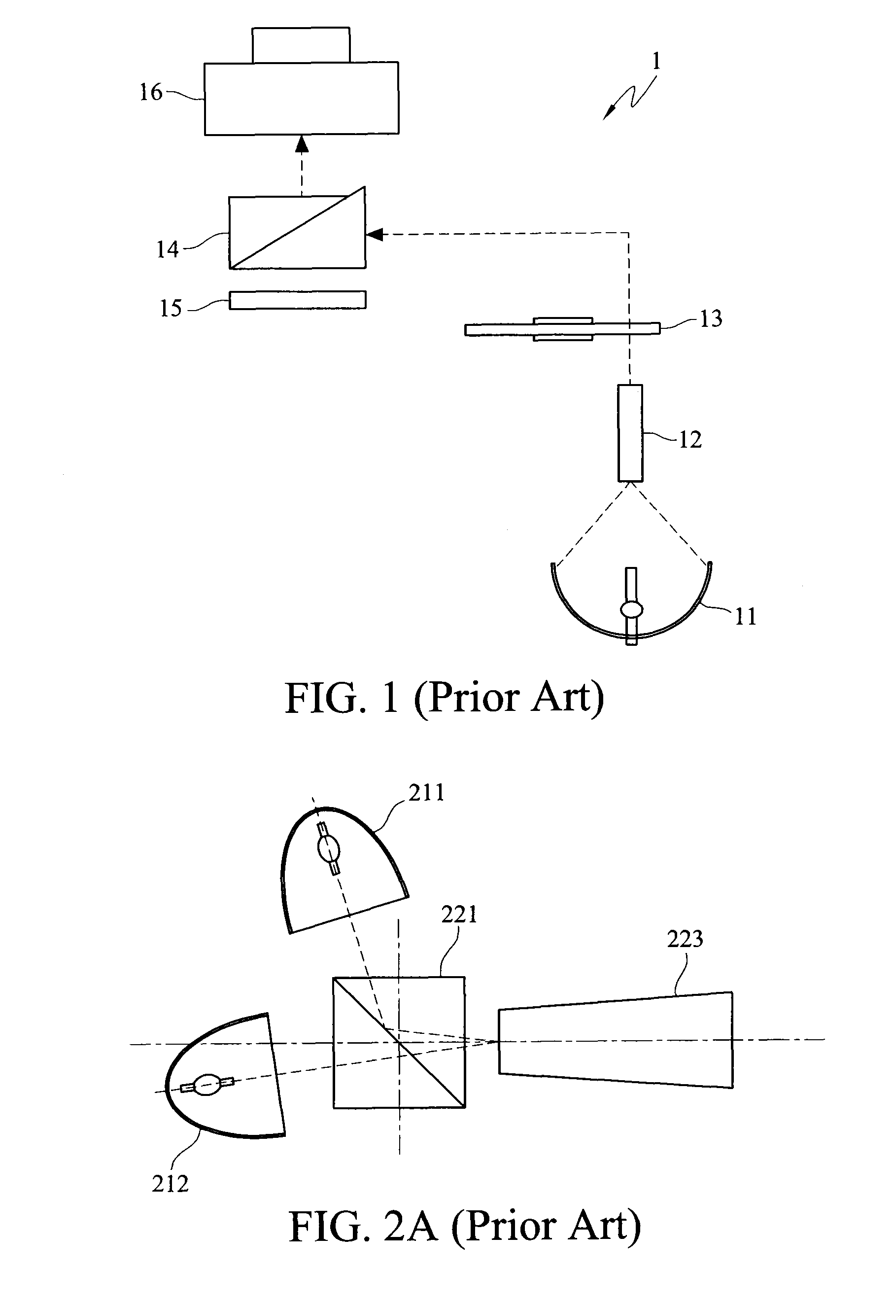
However, the conventional illumination structures have a number of drawbacks.
Conceivably, the more integration rods or optical components that are used in the light integration process, the more light will be lost and the assembling of the projection device will be more complicated.
Furthermore, the conventional arrangement of the light sources described above presents the difficulty in heat dissipation management.
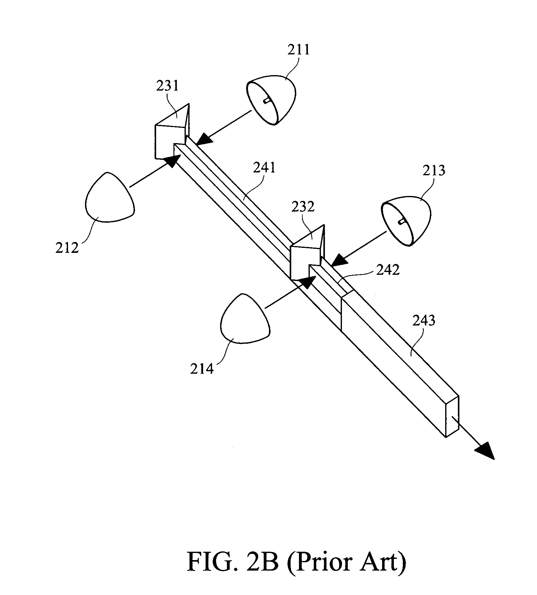
However, in the conventional illumination structure shown in FIG. 2B, all the light sources are disposed at the same horizontal level, which makes it relatively difficult to arrange a number of fans and is also unfavorable for arrangement of elements within the projection device.
Consequently, unsmooth air circulation occurs and brings about poor heat dissipation, high operation temperature and short life-span of the bulbs.
Moreover, disposing the light sources on the same horizontal level makes it difficult to replace light sources, so that the maintenance cost is increased.

Method used


Image

  • Light integration apparatus for use in a projection device
  • Light integration apparatus for use in a projection device
  • Light integration apparatus for use in a projection device

Examples


Embodiment Construction

[0022]In the following description, the light integration apparatus of the present invention will be explained with reference to embodiments thereof. However, these embodiments are not intended to limit the present invention to any specific environment, applications or particular implementations described in these embodiments. The description of these embodiments is only for purpose of illustration rather than limitation. It should be appreciated that in the following embodiments and the attached drawings, elements not related directly to the present invention are omitted from depiction; and dimensions of elements depicted are only for ease of understanding, but not for limitation.

[0023]FIGS. 3A and 3B illustrate the first embodiment of the light integration apparatus of the present invention. The light integration apparatus is for use in a projection device with two light sources (including a first light source 70a and a second light source 70b). FIG. 3A is a schematic plan view of...


PUM


Abstract

A light integration aparatus for use in a projection device is provided. The light integration apparatus comprises the first integration rod and the second integration rod symmetrically disposed with respect to a symmetric axis. The light emerging ends of the first integration rod and the second integration rod are both disposed towards the symmetric axis. Thus, the light is adapted to be guided through the first integration rod and the second integration rod, and emerge from the light emerging ends to travel parallel to the symmetric axis.

Description

CROSS-REFERENCES TO RELATED APPLICATIONS[0001]This non-provisional application claims priority under 35 U.S.C. §119(a) on Patent Application No(s). 097131607 filed in Taiwan, Republic of China on Aug. 19, 2008, the entire contents of which are hereby incorporated by reference.BACKGROUND OF THE INVENTION[0002]1. Field of the Invention[0003]The present invention relates to a light integration apparatus for use in a projection device, and more particularly, to a light integration apparatus that utilizes integration rods to integrate multiple light sources.[0004]2. Descriptions of the Related Art[0005]Currently, projection devices are widely used in offices, houses, conference rooms and places of the like. A projection device generally includes a light source, a prism, a color wheel, an imaging lens and other optical components. Before being projected, light emitted from the light source is integrated by an integration rod and then travels into the color wheel and the imaging lens. Acco...

Claims


Application Information

Patent Timeline
Patent Type & Authority Patents(United States)
IPC IPC(8): G03B21/14
CPCG02B27/0905G02B27/0927G02B27/0994
Inventor HUANG, JUNE-JEI
Owner DELTA ELECTRONICS INC
Learn More