Optical fiber laser

a fiber laser and optical fiber technology, applied in the field can solve the problems of affecting the excitation light source, affecting the output energy of the pulse capable of being produced from the pa b>200/b>, and reducing so as to reduce the number of optical fiber lasers, and save energy

Active Publication Date: 2012-09-18
THE FUJIKURA CABLE WORKS LTD
View PDF17 Cites 0 Cited by
  • Summary
  • Abstract
  • Description
  • Claims
  • Application Information

AI Technical Summary

Benefits of technology

[0036]According to the optical fiber laser as set forth in the above (1), it becomes possible to efficiently eliminate ASE with unnecessary wavelengths that are a cause of a parasitic oscillation. Consequently, it is possible to lengthen the time until an occurrence of a parasitic oscillation. Therefore, the optical fiber laser can store more energy than conventional optical fiber lasers. As a result, when pulsed light is amplified, high-gain amplification can be performed, and hence, a pulsed output with high energy that conventional optical fiber lasers have not been capable of outputting is available.
[0037]Furthermore, in conditions under which a parasitic oscillation has conventionally occurred, a parasitic oscillation does not occur in the optical fiber laser of the present invention. Therefore, it is possible to suppress damage done to the parts of the fiber laser due to the parasitic oscillation. Furthermore, in an optical part such as a filter or an isolator with low power resistance that is conventionally used, these optical parts are heated to a high temperature because of eliminating unnecessary and locally high intense light. Therefore, it has been required a cooling apparatus, or has brought about deterioration in the characteristics of the part. In the optical fiber laser of the present invention, unnecessary light is eliminated with respect to a wavelength distribution. This prevents unnecessary light becoming highly intense. Therefore, the unnecessary light has little effect on optical parts, facilitating cooling. Therefore, it is possible to provide an optical fiber laser which can be used for a long time stable. In addition, in the optical fiber laser according to the above (6), similar operational advantages are obtained.

Problems solved by technology

This brings about a problem in that the pulses reach the excitation light sources 201 and the MO 100 and thereby damage the excitation light source 201 and the MO 100.
This has prevented a high population inversion ratio from being achieved, and hence, the energy of the pulse capable of being output from the PA 200 has been limited.
Consequently, the excitation light source is unlikely to be damaged.
Therefore, in a comparatively high-output optical fiber laser that emits tens of watts or more laser beam, there is a possibility that a parasitic oscillation will occur with this slight reflection or Rayleigh scattering in the fiber functioning as seeds, no matter much the reflection is suppressed.
However, it is impossible to completely suppress the reflected light.
This leads to a possibility of inducing a parasitic oscillation with the slightly remaining reflected light functioning as seeds.
This results in a complex configuration, and hence, lowers efficiency.
However, the light does not unite with the core at all.
This leads to a possibility of a parasitic oscillation.

Method used


Image

  • Optical fiber laser
  • Optical fiber laser
  • Optical fiber laser

Examples


example 1

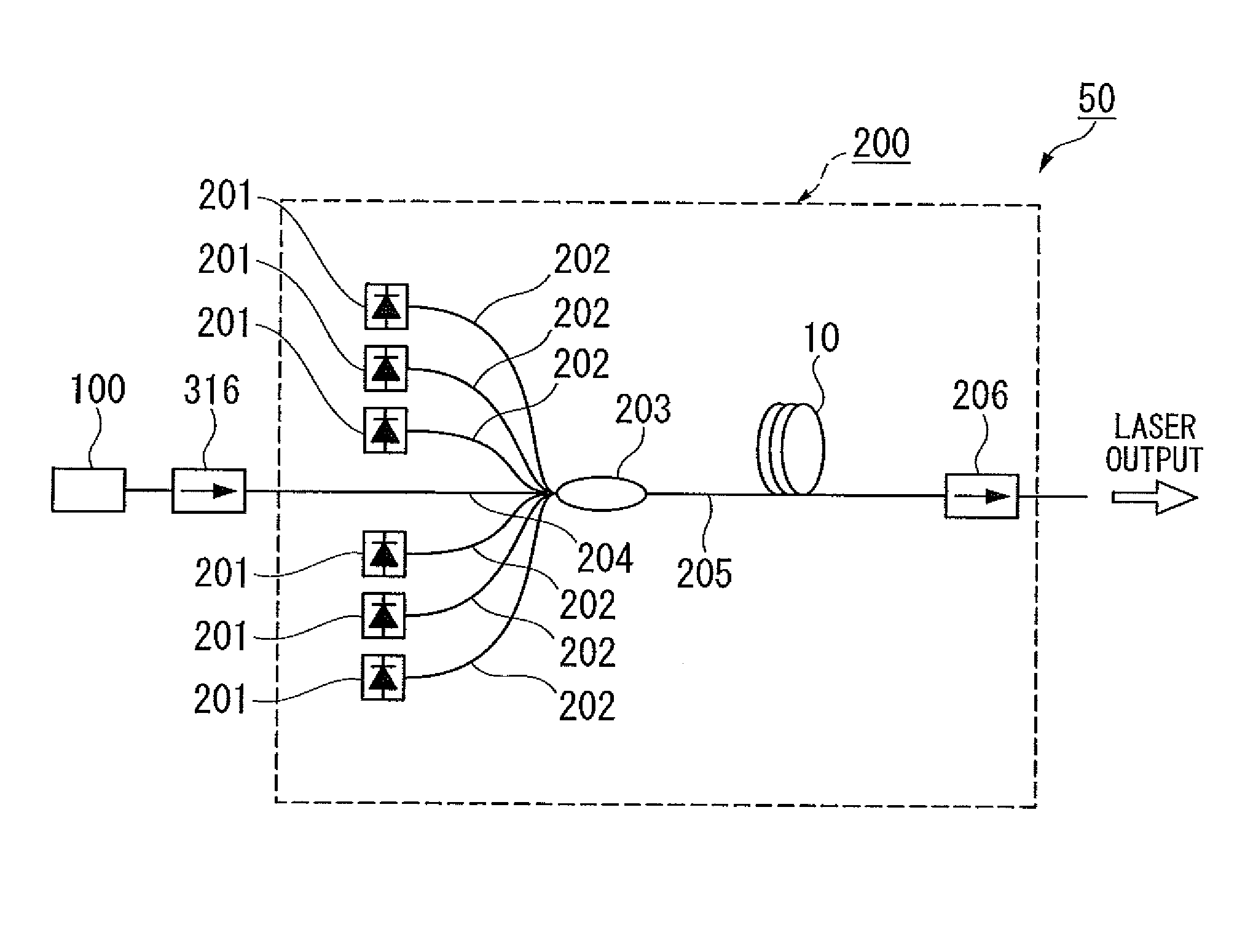
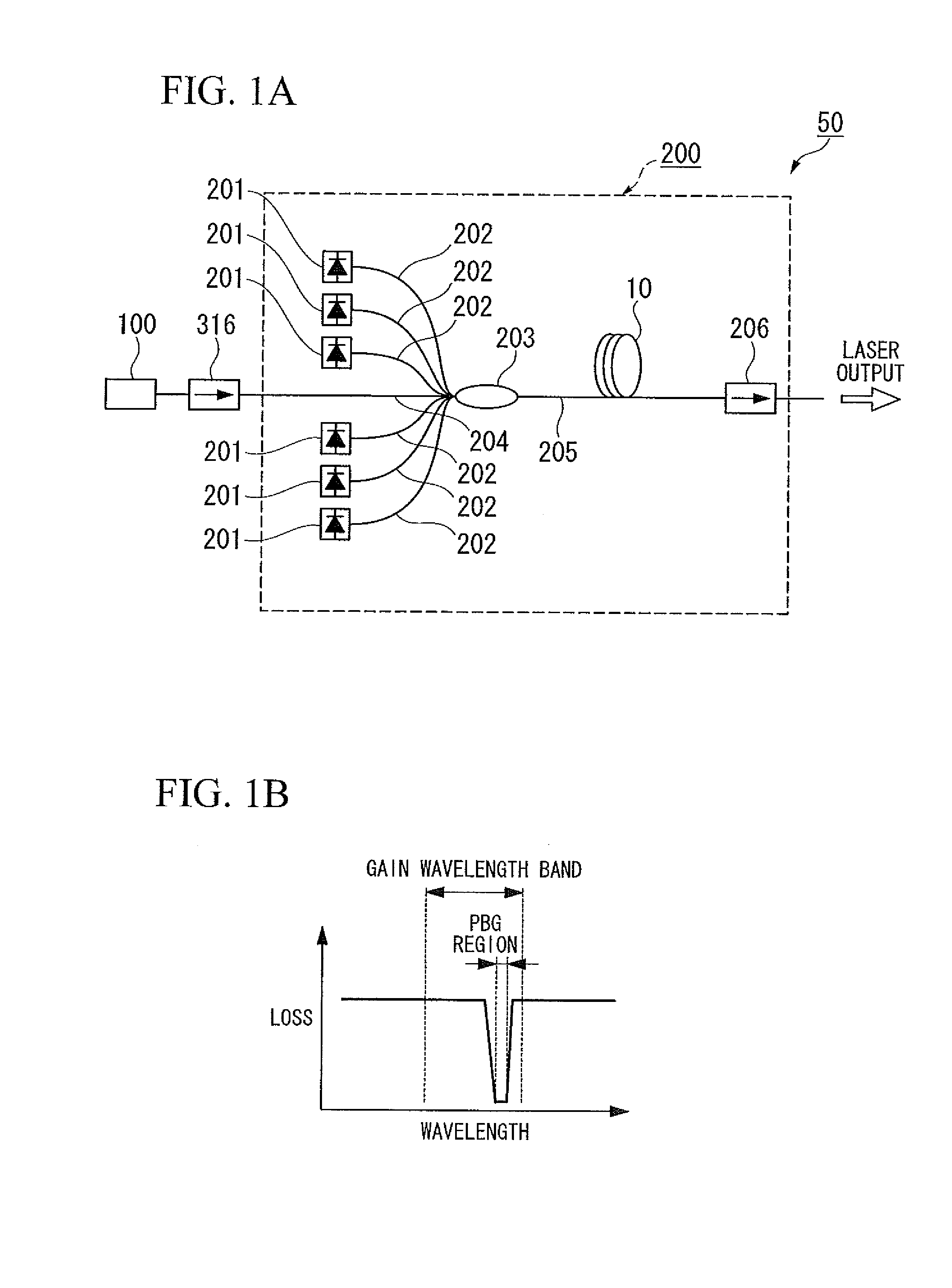
[0146]An optical fiber laser was constructed as shown in FIG. 1A.

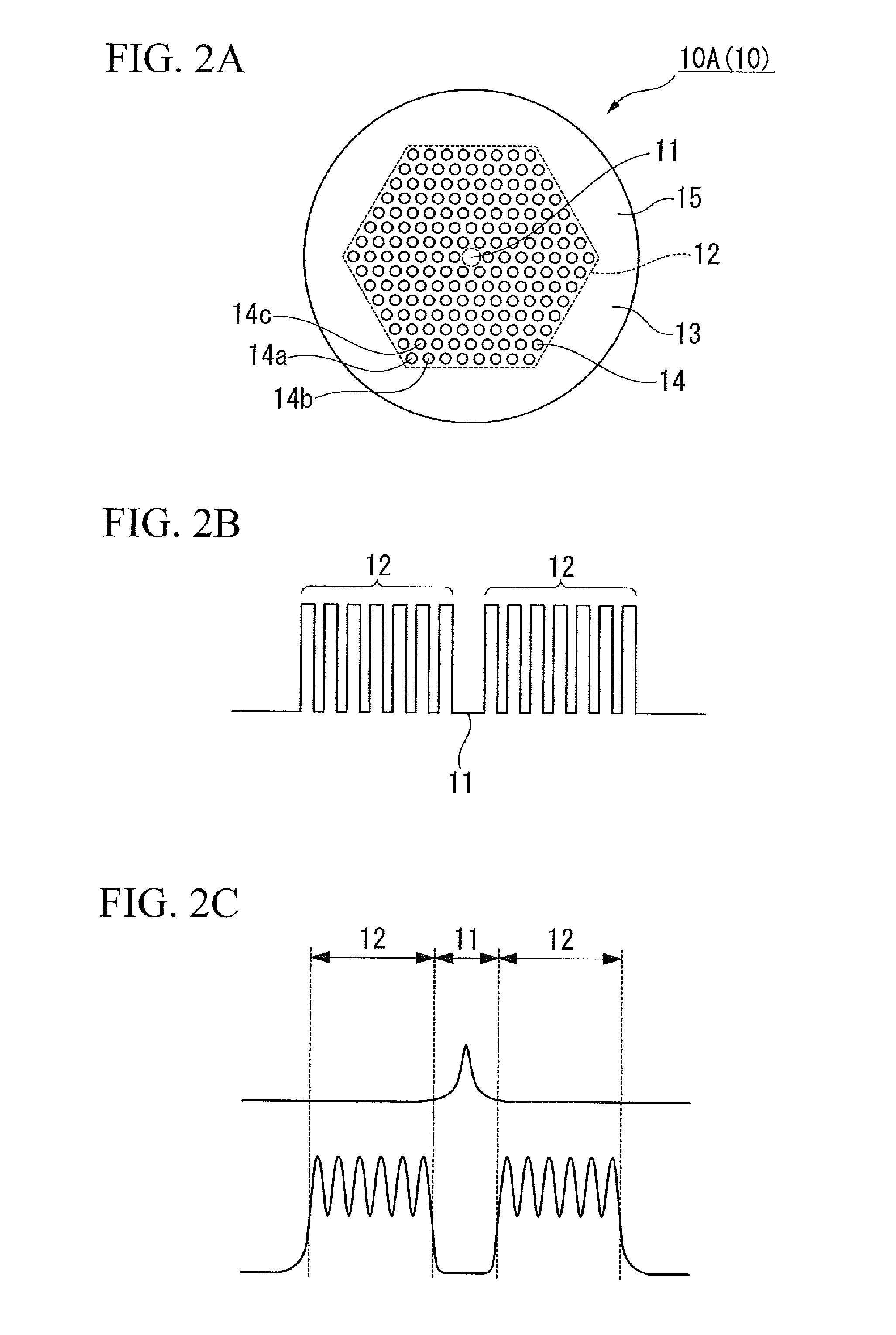
[0147]First, as a photonic bandgap fiber, an optical fiber was fabricated that had the cross-sectional configuration as shown in FIG. 2A and the characteristics shown in FIGS. 2B, 2C. The core portion was doped with Yb ions. The core portion was fabricated so that the wavelength region in which a parasitic oscillation is most likely to occur, that is, the vicinity of 1030 nm to 1050 nm, which is a maximum gain wavelength region of the optical fiber doped with Yb ions, was excluded from the bandgap region, and that 1064 nm, which is a signal wavelength, was in the bandgap region. To be more specific, pure silica glass, which was fabricated into a core portion with a relative index difference Δc of 0% from pure silica glass and with a diameter d of 7.0 μm, was doped with Yb ions. The core portion was coated with a first cladding made of pure silica glass with a diameter of 125 μm. Around a core portion of the first cladd...

example 2

[0151]An optical fiber laser was fabricated similarly to Example 1, the exception being that the photonic bandgap fiber (hereinafter, sometimes referred to as PBGF) shown in FIGS. 3A to 3C was used instead of the PBGF used in Example 1. In the PBGF of the present example, the first layer (the innermost first layer) of the periodic structure of the PBGF of Example 1 was removed, and pure silica was used instead. At the center, pure silica glass was doped with ytterbium oxide to be functioned as an amplifying medium. Furthermore, the center was doped with aluminum oxide to form a core portion with a relative index difference of 0.3% from pure silica and with a diameter of 6 μm. The high refractive index portions had a relative index difference of 2.6% from pure silica glass. Each of the high refractive index portions had a diameter of 4.8 μm, and the distance therebetween was 6 μm. The first cladding was configured to have a diameter of 125 μm. A layer of fluorine-based ultraviolet-cu...

example 3

[0165]The PBGF of Comparative Example 2 was modified to have an increased number only of layers of the periodic structure so as to allow more components to be guided through the periodic structure, to thereby fabricate a PBGF capable of securing a connection loss of approximately 25 dB on the entrance side and the exit side. The PBGF had a core portion with a diameter of 6 μm, a first cladding with a diameter of 125 μm, and a core absorption amount of 1200 dB / m at a wavelength of 976 nm. The PBGF was used to construct an optical fiber laser similarly to in Example 1. This was used as the optical fiber laser of Example 3. In the optical fiber laser, the time from the injection of the excitation lights to the occurrence of a parasitic oscillation was measured similarly to in Example 1.

[0166]As a result, a parasitic oscillation was observed at approximately 60 μs.


PUM


Abstract

An optical fiber laser including: a master oscillator; and a power amplifier, the power amplifier including: a plurality of excitation light sources; excitation ports each of which is connected to the excitation light sources and which an excitation light emitted from each of the excitation light source enters; a signal port which a laser beam emitted from the master oscillator enters; an optical coupler with an exit port that outputs the excitation lights from the excitation ports together with the laser beam from the signal port; and an optical fiber connected to the exit port, in which the optical fiber is a photonic bandgap fiber, and the optical fiber has a loss wavelength characteristic in that a photonic bandgap region is narrower than a gain wavelength band in a graph with an axis of abscissa representing a wavelength and an axis of ordinate representing a loss amount.

Description

CROSS REFERENCE TO RELATED APPLICATIONS[0001]This application is a continuation application based on a PCT Patent Application No. PCT / JP2009 / 052918, filed Feb. 19, 2009, whose priority is claimed on Japanese Patent Application No. 2008-038005 filed Feb. 19, 2008, the entire content of which are hereby incorporated by reference.BACKGROUND OF THE INVENTION[0002]1. Field of the Invention[0003]The present invention relates to an optical fiber laser, more particularly to an optical fiber laser in which a photonic bandgap fiber adjusted to produce a photonic bandgap region only in a signal wavelength region is used, and a parasitic oscillation is suppressed.[0004]2. Description of the Related Art[0005]Recent years have seen advances in the high output of fiber lasers. Optical fiber lasers with an output over kW have been developed. Such optical fiber lasers with a high output have come to be utilized in a variety of fields such as in finishing machines, medical equipment, and measuring eq...

Claims


Application Information

Patent Timeline
Patent Type & Authority Patents(United States)
IPC IPC(8): H01S3/30
CPCH01S3/2308G02B6/02338G02B6/02357G02B6/0238H01S3/06729H01S3/06741H01S3/06754H01S3/06791H01S3/09408
Inventor KITABAYASHI, TOMOHARU
Owner THE FUJIKURA CABLE WORKS LTD
Why Eureka
Try Eureka