Optical fiber laser
a fiber laser and optical fiber technology, applied in the field can solve the problems of affecting the excitation light source, affecting the output energy of the pulse capable of being produced from the pa b>200/b>, and reducing so as to reduce the number of optical fiber lasers, and save energy
- Summary
- Abstract
- Description
- Claims
- Application Information
AI Technical Summary
Benefits of technology
Problems solved by technology
Method used
Image
Examples
first embodiment
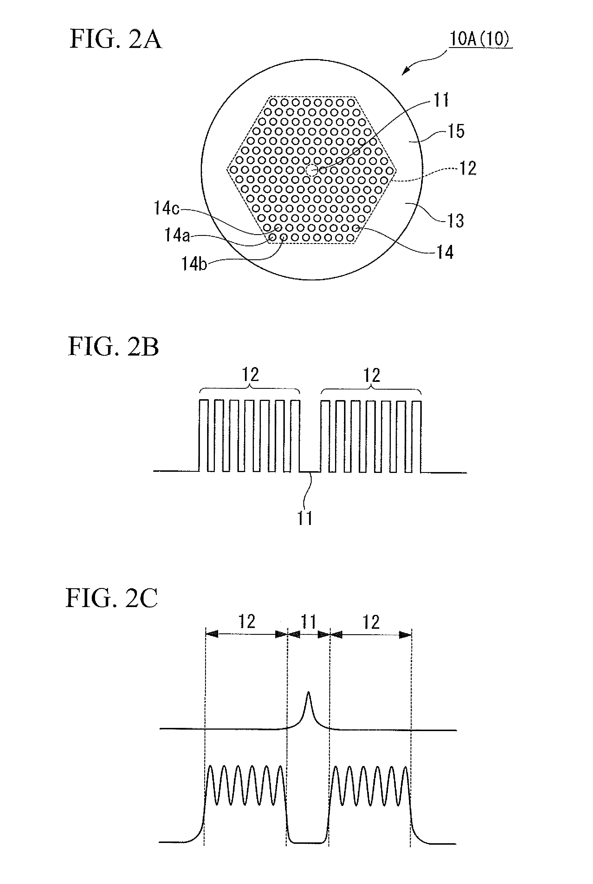
[0087]Hereunder is a detailed description of the present invention with reference to the drawings. However, the present invention is not limited to this. Various modifications can be made without departing from the sprit or scope of the present invention.
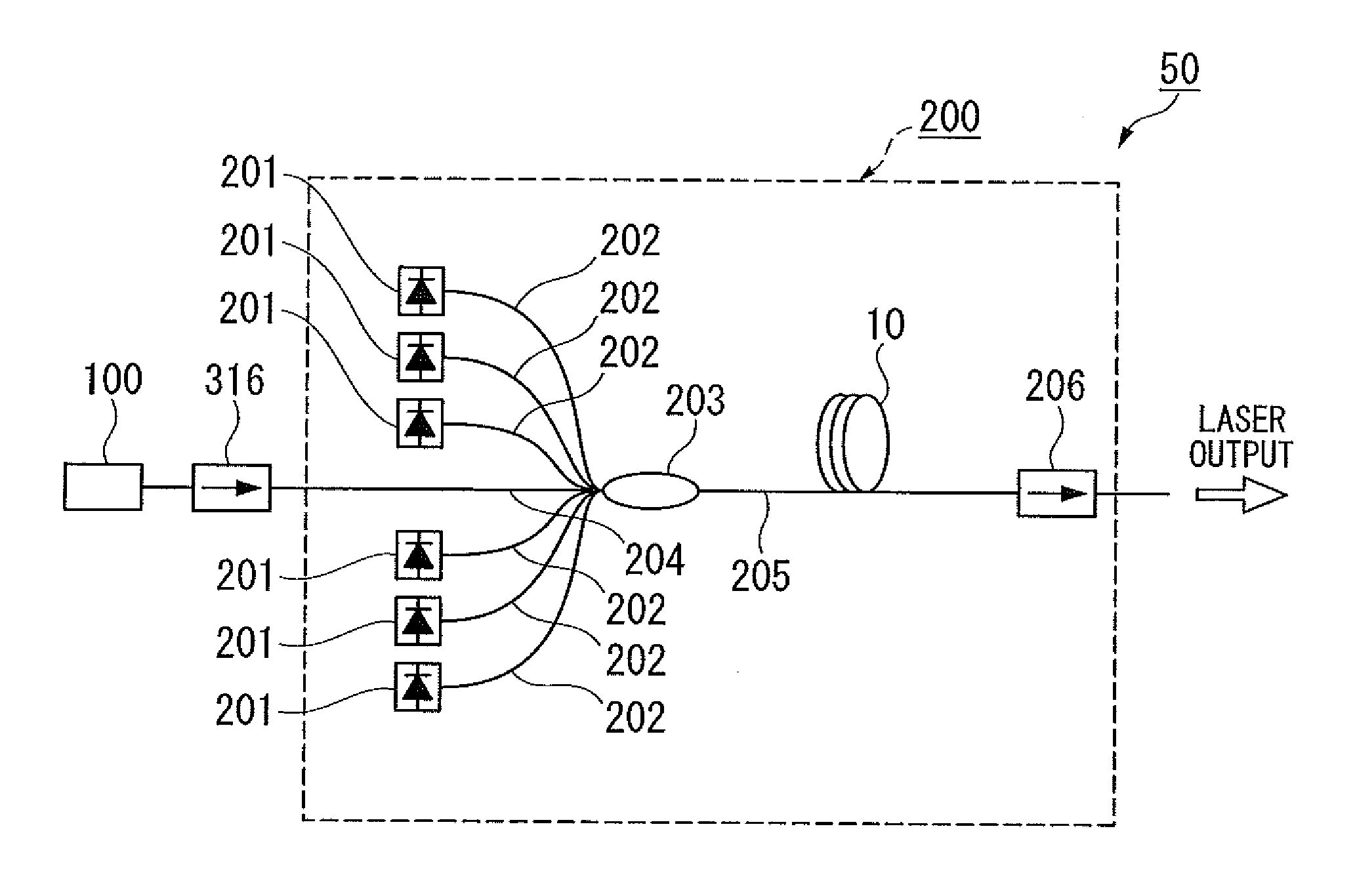
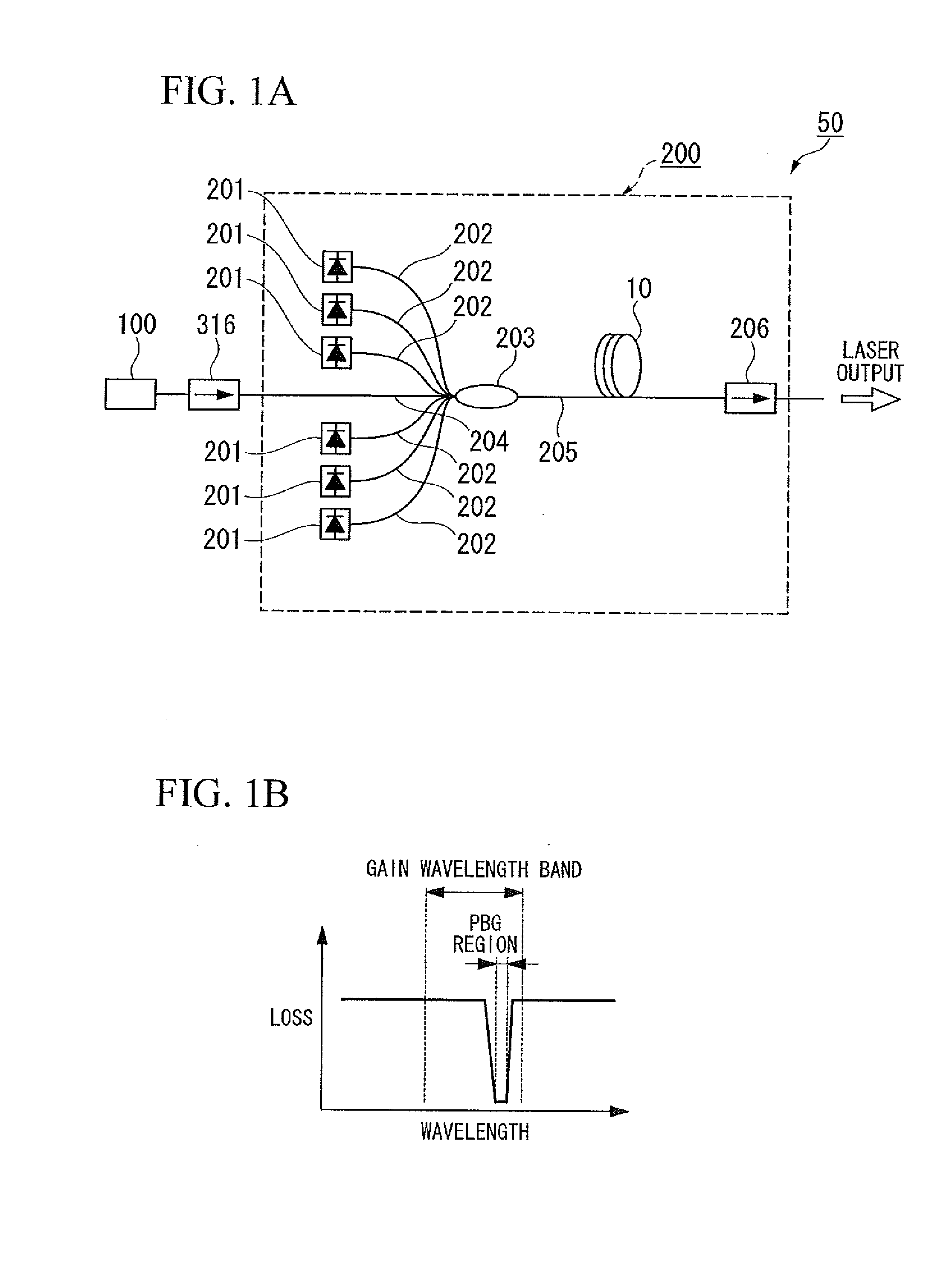
[0088]FIG. 1A is a configuration diagram schematically showing an optical fiber laser 50 according to a first embodiment of the present invention. FIG. 1B shows a loss wavelength characteristic of an optical fiber 10 used in the optical fiber laser 50 of the present embodiment.
[0089]Similarly to the optical fiber laser shown in FIG. 14, the optical fiber laser of the present embodiment is an optical fiber laser 50 with the MOPA system in which a master oscillator (hereinafter, sometimes referred to as MO) 100 of a laser oscillator for producing a seed beam is connected with a power amplifier (hereinafter, sometimes referred to as PA) 200 that amplifies and outputs the laser beam emitted from the MO 100. The power amplifier is at the...
second embodiment
[0106]FIG. 3A is a cross-sectional view schematically showing an optical fiber 10B (10) mounted in an optical fiber laser according to a second embodiment. FIG. 3B is a diagram showing a refractive index profile of the optical fiber 10B used in the present embodiment. FIG. 3C is a diagram showing an electric field distribution of the optical fiber 10B used in the present embodiment.
[0107]The optical fiber laser of the present invention is different from the optical fiber laser of the first embodiment in that the optical fiber 10B is used that has a cross-section shown in FIG. 3A, and also has the refractive index profile shown in FIG. 3B and the electric field distribution shown in FIG. 3C.
[0108]In the optical fiber 10B used in the present embodiment, the first layer (the innermost layer) of the high refractive index portion in the periodic structure of the optical fiber 10A of the first embodiment is removed, and a region 21a in which pure silica is arranged is formed. In the regio...
third embodiment
[0117]FIG. 4A is a cross-sectional view schematically showing an optical fiber 10C (10) mounted in an optical fiber laser according to a third embodiment. FIG. 4B is a diagram showing a refractive index profile of the optical fiber 10C used in the present embodiment. FIG. 4C is a diagram showing an electric field distribution of the optical fiber 10C used in the present embodiment.
[0118]The optical fiber laser of the present embodiment is different from the optical fiber laser of the first embodiment in that the optical fiber 10C is used that has a cross-section shown in FIG. 4A, and also has the refractive index profile shown in FIG. 4B and the electric field distribution shown in FIG. 4C.
[0119]In the optical fiber 10C used in the present embodiment, the inner first and second layers (the portion in the vicinity of the core) of the periodic structure portion 12 of the first embodiment is removed, and a region 31a made of pure silica is formed. In the region 31a, there is formed a c...
PUM
 Abstract
Description
Claims
Application Information
 - R&D
- Intellectual Property
- Life Sciences
- Materials
- Tech Scout
- Unparalleled Data Quality
- Higher Quality Content
- 60% Fewer Hallucinations
Browse by: Latest US Patents, China's latest patents, Technical Efficacy Thesaurus, Application Domain, Technology Topic, Popular Technical Reports.
© 2025 PatSnap. All rights reserved.Legal|Privacy policy|Modern Slavery Act Transparency Statement|Sitemap|About US| Contact US: help@patsnap.com


