
Determination of feature boundaries in a digital representation of an anatomical structure

a digital representation and feature boundary technology, applied in image analysis, image enhancement, instruments, etc., can solve the problems of affecting the efficiency of analysis of the amount of data presented to the physician, significant limitations of current automated techniques, and the inability to accurately determine the boundary of the feature boundary in the digital representation of the anatomical structur

Active Publication Date: 2005-04-14
UNITED STATES OF AMERICA
View PDF13 Cites 141 Cited by
  • Summary
  • Abstract
  • Description
  • Claims
  • Application Information

AI Technical Summary

Benefits of technology

The patent describes techniques for analyzing digital representations of anatomical structures to determine the boundaries of features within them. This can be useful for identifying polyp boundaries in a virtual colon. The techniques can be applied in both two-dimensional and three-dimensional scenarios. After the boundary is determined, various feature characteristics can be computed to classify the feature as of interest or not. The patent also mentions user interfaces for depicting features. Overall, the patent provides a technical solution for accurately analyzing anatomical structures and their features.

Problems solved by technology

However, as the number of slices increases, the amount of data presented to the physician becomes more difficult to efficiently analyze.
Although progress has been made in employing software to assist in detection of anatomical features, there are significant limitations to the current automated techniques.
For example, one problem consistently plaguing such systems is the overabundance of false positives when detecting features of interest.
However, the software also tends to incorrectly identify too many structures as features of interest (i.e., the software exhibits poor specificity).
False positives are troublesome because any identified positives must be considered and evaluated by a human classifier (such as the physician or a technician).
Even if a feature can be quickly dismissed as a false positive, too many false positives consume an inordinate amount of time and limit the usefulness of the software-based approach.

Method used


Image

  • Determination of feature boundaries in a digital representation of an anatomical structure
  • Determination of feature boundaries in a digital representation of an anatomical structure
  • Determination of feature boundaries in a digital representation of an anatomical structure

Examples


example 1

Exemplary System for Determining Boundary of a Feature in a Digital Representation of an Anatomical Structure

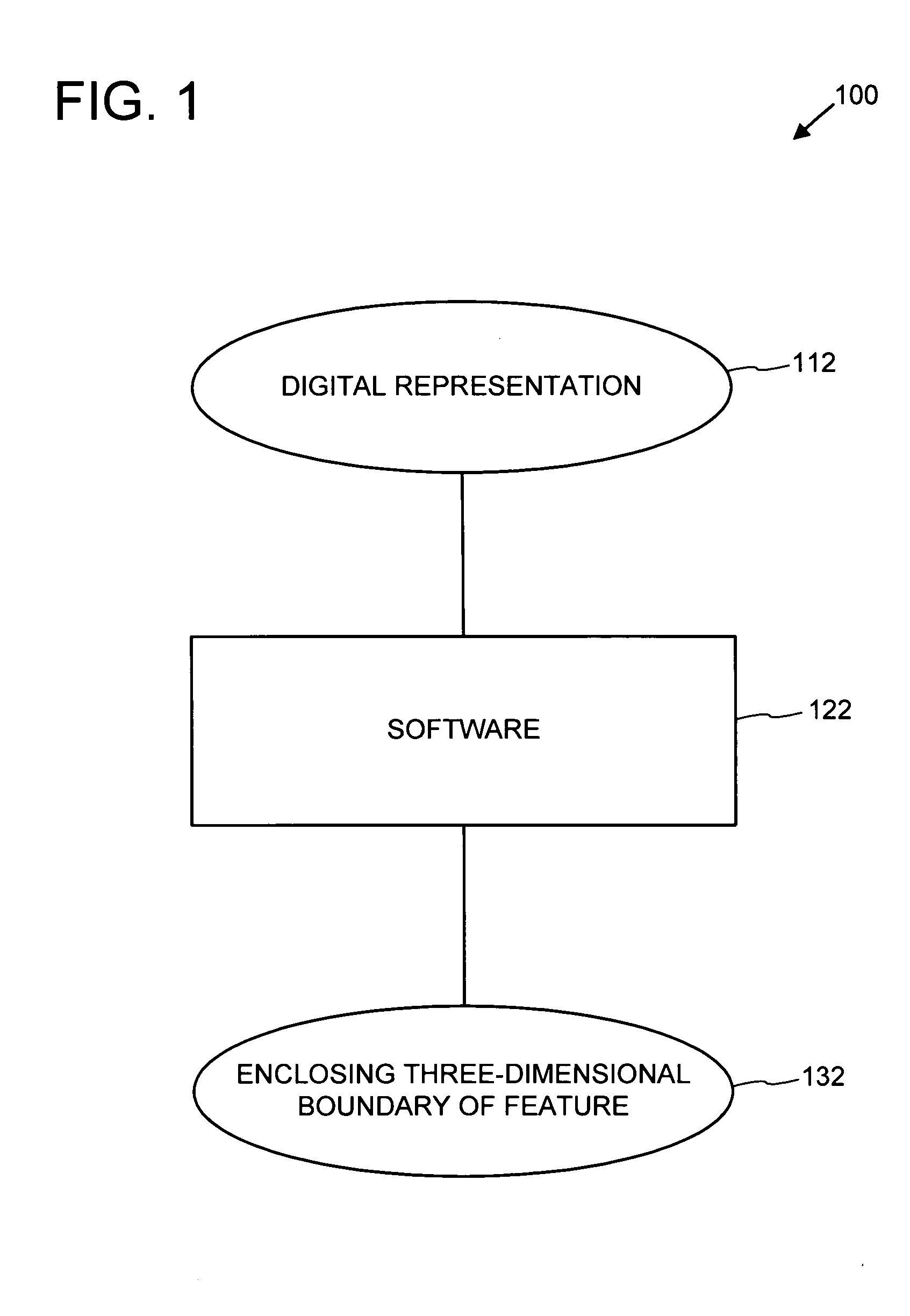
FIG. 1 shows an exemplary system 100 for determining an enclosing three-dimensional boundary 132 of a feature in a digital representation 112 of at least a portion of an anatomical structure.

The digital representation 112 is processed by the software 122 to determine the enclosing three-dimensional boundary 132 of at least one feature represented in the digital representation 112. The software 122 can employ any combination of the technologies described herein.

In any of the examples described herein, a variety of feature characteristics can be determined via its enclosing boundaries 132 if desired. For example, geometric and volumetric characteristics can be determined via the enclosing boundaries.

Further, the boundaries 132 can be depicted via user interfaces. For example, a graphical depiction of a feature via its enclosing three-dimensional boundary can be displayed...

example 2

Exemplary Method for Determining Boundary of a Feature in a Digital Representation of an Anatomical Structure

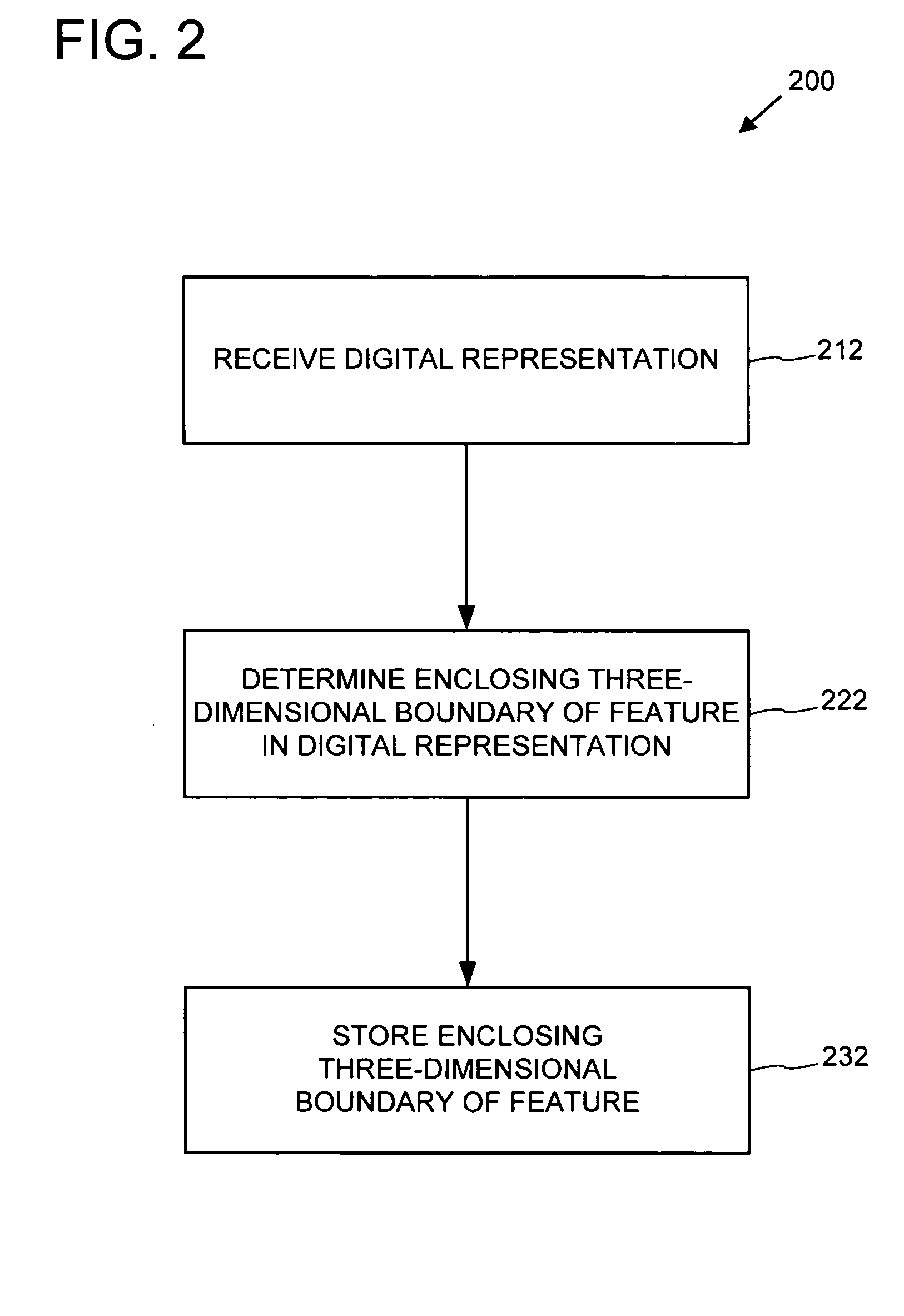
FIG. 2 shows an exemplary method 200 for determining an enclosing three-dimensional boundary of a feature represented in the digital representation. The method can be performed, for example, by the system 100 of FIG. 1. The method 200 and any of the other methods described herein can be performed by computer-executable instructions stored on one or more computer-readable media.

At 212, a digital representation (e.g., the digital representation 112 of FIG. 1) representing at least one feature in at least a portion of an anatomical structure is received.

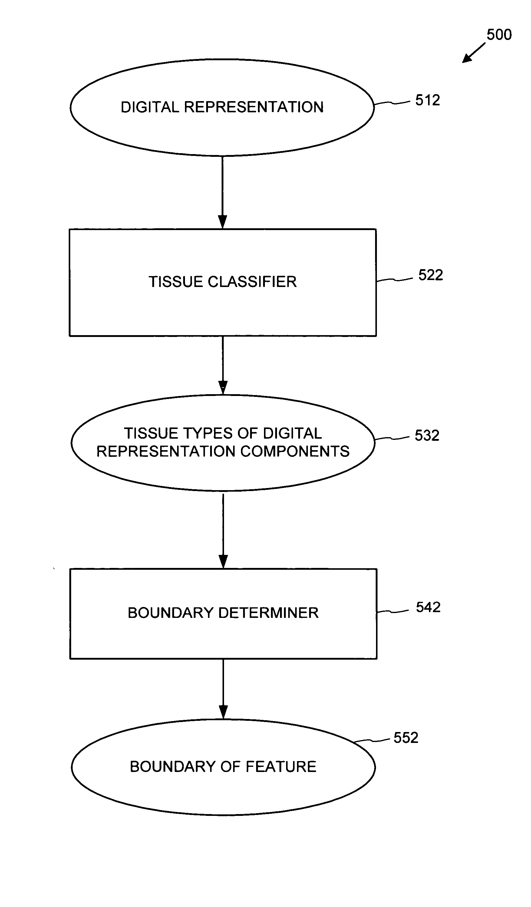
At 222, an enclosing three-dimensional boundary of the feature in the digital representation is determined. As described in the examples, a variety of techniques can be used for determining such a boundary. For example, tissue types can be determined, and a boundary can be based on the tissue types.

At 232, the enclosing th...

example 3

Exemplary System for Classifying Candidates in a Digital Representation via Boundary

FIG. 3 shows an exemplary system 300 for processing a plurality of candidate features of interest with software to classify the candidate features of interest. A plurality of feature candidates 312 are received by the software 322, which indicates the classifications of interest 332 or not of interest 334. For example, in a system for identifying polyps in a virtual colon, a feature can be classified as being of interest (for example, a polyp) or not of interest (for example, not a polyp). Additional classifications are possible (e.g., classifying a candidate feature as being a normal anatomical structure).

The software 322 can employ any combination of the technologies described herein.

The feature candidates 312 can take a variety of forms. For example, other software (not shown) can scan a digital representation of at least a portion of an anatomical structure and detect features as candidate f...


PUM


Abstract

A virtual anatomical structure can be analyzed to determine enclosing three-dimensional boundaries of features therein. Various techniques can be used to determine tissue types in the virtual anatomical structure. For example, tissue types can be determined via an iso-boundary between lumen and air in the virtual anatomical structure and a fuzzy clustering approach. Based on the tissue type determination, a deformable model approach can be used to determine an enclosing three-dimensional boundary of a feature in the virtual anatomical structure. The enclosing three-dimensional boundary can be used to determine characteristics of the feature and classify it as of interest or not of interest.

Description

TECHNICAL FIELD The field relates to software analysis of images. BACKGROUND Technology for non-invasive observation of soft tissues of the body has provided significant advances in the field of medicine. For example, a number of techniques now make it possible to routinely image anatomical structures such as the heart, colon, bronchus, and esophagus within the body. The widespread availability of skilled technicians and reduction in cost of the necessary equipment has encouraged the use of non-invasive imaging as a part of routine preventive care. Non-invasive imaging reduces the risk of observation-related injury or complication and reduces discomfort and inconvenience for the observed patient. These advantages encourage patients to undergo more frequent screening and permits earlier detection of potentially life-threatening conditions. For example, malignant or premalignant conditions can be identified and diagnosed at an early stage, when treatment is more likely to be succes...

Claims


Application Information

Patent Timeline
Patent Type & Authority Applications(United States)
IPC IPC(8): G06K9/00G06K9/34G06K9/46G06T5/00
CPCG06K9/00201G06T7/0012G06T7/0083G06T2207/30032G06T7/0097G06T2207/10081G06T7/0089G06T7/12G06T7/149G06T7/174G06V20/64
Inventor YAO, JIANHUASUMMERS, RONALD M.
Owner UNITED STATES OF AMERICA
Learn More