Vacuum control system

a vacuum control system and vacuum vessel technology, applied in fluid pressure control, separation processes, instruments, etc., can solve the problems of low efficiency of suppressing or removing condensation of vaporized components degassed into the vacuum vessel through the gas permeation diaphragm in the vacuum exhaust path, and cannot be said exactly that the vacuum degree is kept constant, so as to achieve effective and accurate removal of vaporized components and maintain the vacuum degree in the vacuum vessel

Active Publication Date: 2005-04-14
ERC
View PDF10 Cites 22 Cited by
  • Summary
  • Abstract
  • Description
  • Claims
  • Application Information

AI Technical Summary

Benefits of technology

[0010] Accordingly, it is an object of the present invention to provide a vacuum control system capable of continuously adjusting the amount of exhaust of a vacuum pump by controlling the rotatory power of the vacuum pump motor, allowing the degree of vacuum in a vacuum vessel to be kept constant, effectively and accurately removing vaporized components degassed into the vacuum vessel through a gas permeation diaphragm by stably introducing a very small amount of air into a vacuum exhaust path, and thus operating stably, and a vacuum degassing apparatus employing the vacuum control system.

Problems solved by technology

However, in the conventional vacuum control method, even if the vacuum pump is activated intermittently or the switching valve is activated, the degree of vacuum in the vacuum vessel including the gas permeation diaphragm repeatedly goes up and down with a constant width (range), so that it cannot be said exactly that the degree of vacuum is kept constant.
However, from the viewpoint of cost, effects, and stability, the optimum solving means has not been provided yet.
Furthermore, during unattended operation with automation of analytical instruments, stable activation of the degassing apparatus, etc. is required, but in the conventional degassing apparatuses or vacuum control systems, an efficiency of suppressing or removing condensation of vaporized components degassed into the vacuum vessel through the gas permeation diaphragm in the vacuum exhaust path is low, and thus they are not practical.
That is, in a method of introducing a very small amount of air into the vacuum exhaust path, which has been attempted conventionally, there are problems in that the introduction position is not proper, determination of resistance values of a resistance tube for introducing the small amount of air reproducibly is difficult, or variation of the resistance values is caused.

Method used


Image

  • Vacuum control system
  • Vacuum control system
  • Vacuum control system

Examples


Embodiment Construction

[0018] Now, preferred embodiments of the present invention will be described in detail with reference to the accompanying drawings, but the present invention is not limited to the embodiments.

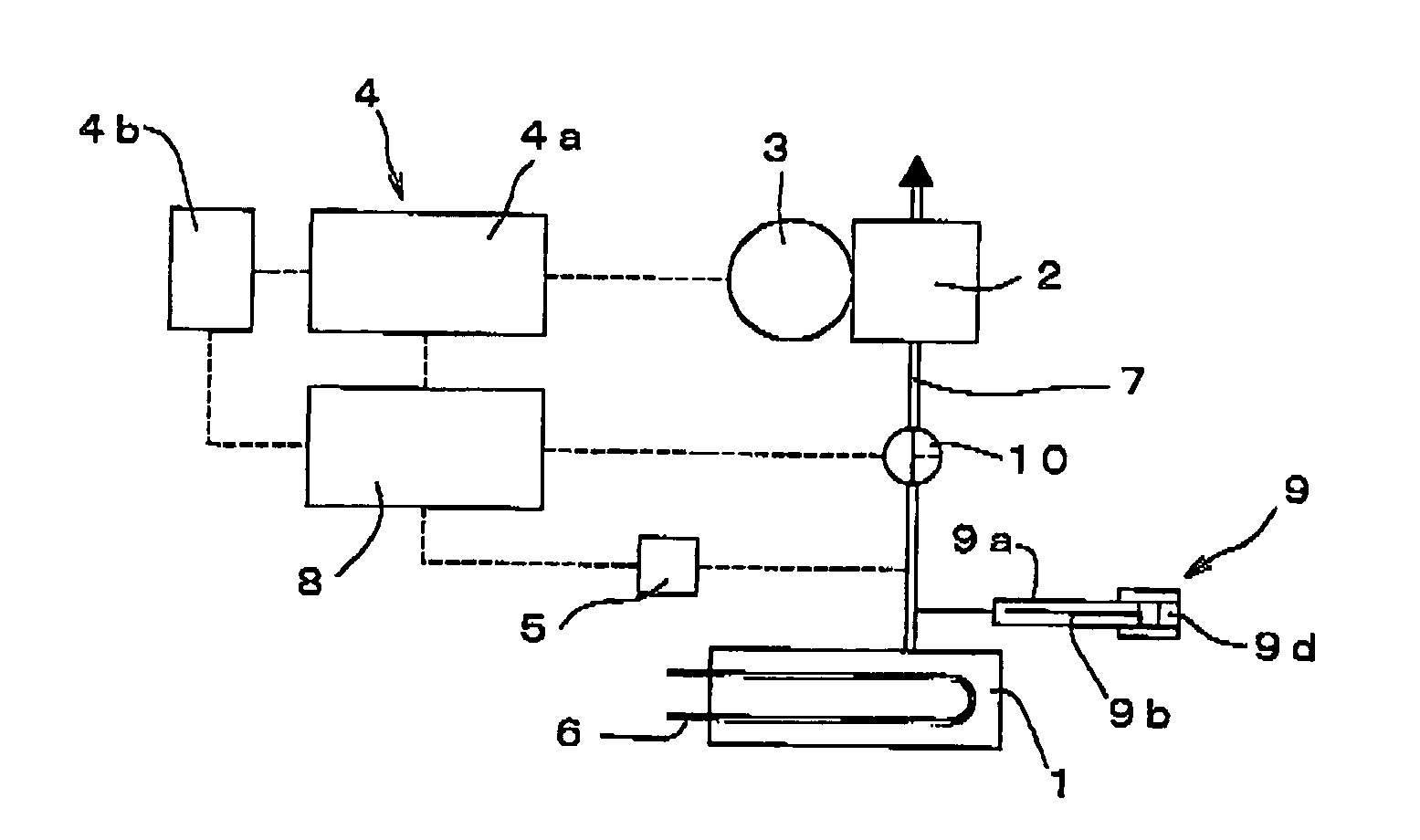
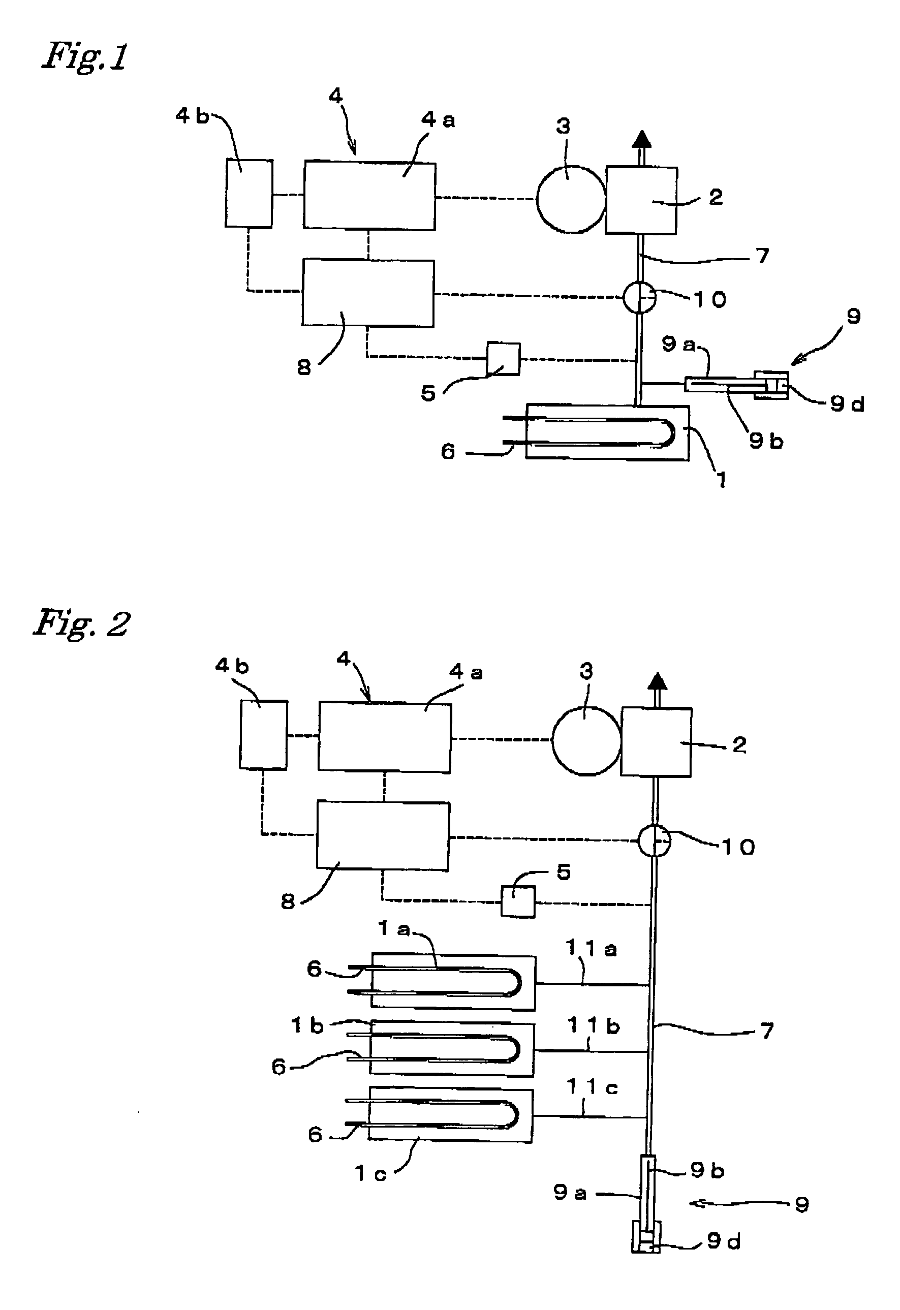
[0019] A vacuum control system according to the present invention, as shown in FIGS. 1 and 2, basically comprises a vacuum vessel 1, an exhaust vacuum pump 2 for decompressing the inside of the vacuum vessel 1, a DC brushless motor 3 for driving the exhaust vacuum pump 2, a power source unit 4 for activating the DC brushless motor 3, and a pressure sensor 5 for monitoring and measuring the pressure (the degree of vacuum) in the vacuum vessel 1 and feeding back the measurement data (output signal) to the power source unit 4. By providing a gas permeation diaphragm 6 such as a degassing tube in the vacuum vessel 1 in the vacuum control system, the vacuum control system can be used as a vacuum degassing apparatus.

[0020] In addition, FIGS. 1 and 2 show embodiments of the vacuum control system fit...


PUM

PropertyMeasurementUnit
pressureaaaaaaaaaa
flow rateaaaaaaaaaa
circulation resistanceaaaaaaaaaa

Abstract

There is provided a vacuum control system for allowing the degree of vacuum in a vacuum vessel to be kept constant, effectively and accurately removing vaporized components degassed into the vacuum vessel through a gas permeation diaphragm by stably introducing a very small amount of air into a vacuum exhaust path, and thus operating stably, and a vacuum degassing apparatus employing the vacuum control system. The vacuum control system controls the rotatory power of a DC brushless motor, continuously controls displacement of a vacuum pump, and thus keeps the degree of vacuum in a vacuum vessel constant, by decompressing the inside of the vacuum vessel using an exhaust vacuum pump which operates with the DC brushless motor, monitoring the inside pressure of the vacuum vessel using a pressure sensor, and controlling a voltage applied to the DC brushless motor on the basis of an output signal resulting from measurement of the inside pressure of the vacuum vessel by the pressure sensor.

Description

BACKGROUND OF THE INVENTION [0001] 1. Field of Invention [0002] The present invention relates to a vacuum control system for keeping degree of vacuum accurate and constant in an instrument requiring vacuum (decompression), and specifically to a vacuum control system suitable for a vacuum degassing apparatus for removing dissolved gas from liquid isolated with a gas permeation diaphragm by reducing inside pressure of a vacuum vessel being fitted into a precision analytical instrument and having the gas permeation diaphragm by means of an exhaust vacuum pump, and a vacuum degassing apparatus employing the vacuum control system. [0003] 2. Description of the Related Art [0004] Degassing apparatuses for removing or reducing dissolved gas in a liquid (hereinafter, this is referred to as “degassing”) were conventionally widely used to secure stability or measurement accuracy of precision analytical instruments using a liquid. Since most of them have a basic structure that gas dissolved in ...

Claims


Application Information

Patent Timeline
Patent Type & Authority Applications(United States)
IPC IPC(8): A61M1/00B01D19/00F04B49/06B01D61/00F04B37/14G05D16/04G05D16/20
CPCB01D19/0031B01D19/0063G05D16/2066F04B2205/01F04B37/14
Inventor ISHII, YOSHIOTANEMURA, KOJIMATSUMOTO, TOSHIHIKOSHIRATO, KOZO
Owner ERC
Why Eureka
Try Eureka