Shoestring tying apparatus

a technology of shoestring ties and tying rods, which is applied in the direction of snap fasteners, buckles, shoe lace fastenings, etc., can solve the problems of difficult secure operation of the fastening member b>22/b> by rotating the aforementioned rotational cap b>24/b>, and improve the portability and appearance of the shoestring ties. , the effect of low cost and improved portability

Inactive Publication Date: 2005-04-21
SAKABAYASHI TOSHIKI
View PDF23 Cites 155 Cited by
  • Summary
  • Abstract
  • Description
  • Claims
  • Application Information

AI Technical Summary

Benefits of technology

[0021] With the shoestring tying apparatus according to the present invention, the cover member may be formed in the shape of an egg, an ellipse, a grand piano, round, square, or the like, in any desired color, so as to improve the portability and appearance of the shoestring tying apparatus.
[0022] The shoestring tying apparatus according to the present invention has a simple configuration integrally formed of the spring storage member for storing the helical spring serving as a small-sized elastic member, and the ratchet, thereby enabling the shoestring tying apparatus to be manufactured with low costs.
[0023] Furthermore, the aforementioned cover member may include a connection member (in the shape of a key-ring) for detachably connecting the shoestring tying apparatus to the user. In this case, the portability of the shoestring tying apparatus is further improved, and the user can quickly use the shoestring tying apparatus when necessary. Furthermore, this prevents the user from losing the shoestring tying apparatus.
[0024] With the shoestring tying apparatus according to the present invention, the user can fasten the shoestring very quickly and in a sure manner. Furthermore, the shoestring tying apparatus is small in size and easy to use, and also h...

Problems solved by technology

However, with regard to any of the aforementioned arrangements, there is a need to rotate the aforementioned rotational cap 24 several dozen times so as to fasten the shoestring 23, which is troublesome for the u...

Method used


Image

  • Shoestring tying apparatus
  • Shoestring tying apparatus
  • Shoestring tying apparatus

Examples


first embodiment

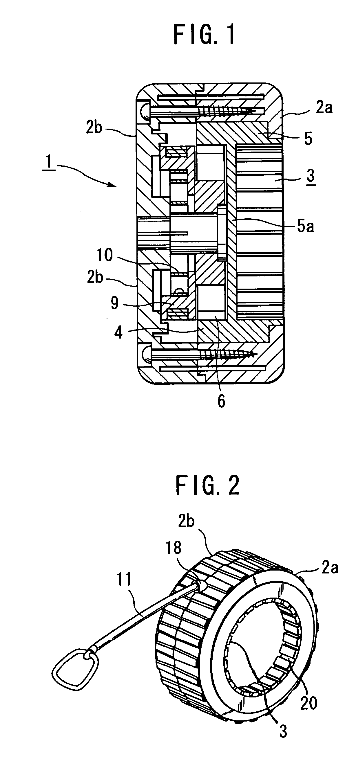
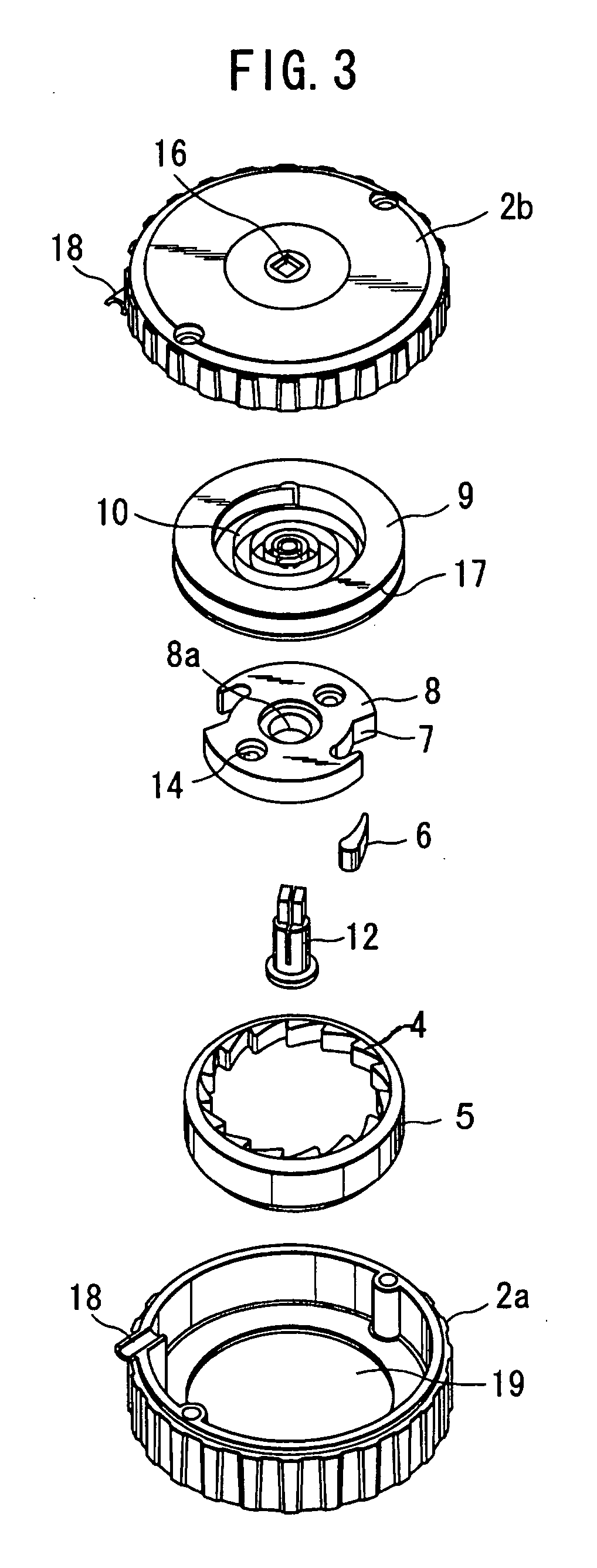
[0040] As shown in FIG. 1, a shoestring tying apparatus 1 shown in FIG. 1 includes a cover 2 (front cover 2a and back cover 2b) formed of colored resin for storing the internal configuration components thereof. The shoestring tying apparatus 1 further comprises a rotational member 5 including a partition 5a, wherein a fitting portion 3 is formed on one side of the partition 5a for connecting the apparatus to a fastening member 22 with a rotational cap (operating member) 24 which is a conventional operating rotor or an outer rotational portion thereof, and including an internal gear 4 formed on the internal circumference (on the other side) of the partition 5a. The driving mechanism of the shoestring tying apparatus 1 comprises a restricting device including a ratchet 8 and a pawl (engaging member) 6 at a pawl storage section 7 of the ratchet 8 for engaging the internal gear 4. A cylindrical spring storage member 9 is in contact with the side of the ratchet 8, and a helical spring (...

second embodiment

[0062] Next, a description will be made of a shoestring tying apparatus with reference to FIGS. 5 through 8.

[0063] As shown in the drawings, a cap (operating member) 324 includes multiple pawls 301 on the inner face thereof for engaging a gear wheel so as to rotate in one direction, includes an internal gear 303 on the inner side of the pawls 301, and includes a gear wheel 302 on the inner side of the internal gear 303 which can move within the cap 324. A hexagonal shaft 314 is fit to the gear wheel 302. Note that the cap 324 can be slidably moved along the hexagonal shaft 314.

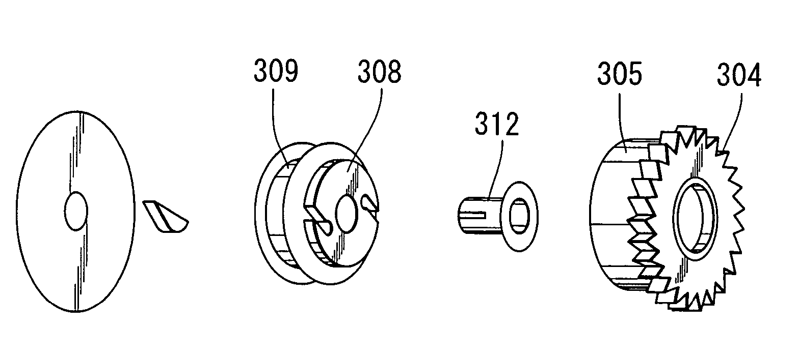
[0064] On the other hand, a rotational member 305 includes an external gear (fitting portion) 304 for engaging the internal gear 303 of the cap 324, an inner spring for forcing the operating cord 11, and a shaft 312 which is rotatably fit to the aforementioned hexagonal shaft 314. The rotational member 305 further includes a ratchet 308 for engaging an internal gear provided on the inner face of rotational m...


PUM


Abstract

A fitting portion of a rotational member of a shoestring tying apparatus is fit to a rotational cap serving as an operating member of a fastening member for winding up and fastening a shoestring. The fitting portion serves as a connection between a driving mechanism and the rotational cap. When the user pulls an operating cord serving as a portion of a driving mechanism, a rotational member is rotated, and a spring included in the rotational member is wound. The rotational cap is rotated through the fitting portion due to rotation of the rotational member, thereby quickly rotating the fastening member. Thus, the fastening member can be rotated several dozen times by an operation in which the operating cord is alternately extracted and retracted several times. This provides a shoestring tying apparatus with excellent portability and appearance for easily and quickly fastening a shoestring in a sure manner.

Description

BACKGROUND OF THE INVENTION [0001] 1. Field of the Invention [0002] The present invention relates to a shoestring tying apparatus for easily fastening a shoestring of a sport shoe or the like in a sure manner without using fastening tension by hand. [0003] 2. Description of the Related Art [0004] Conventionally, a shoestring is laced through eyelets provided on the opening portion of a sport shoe or the like, and both ends of the shoestring are tied tightly at the ankle of the user. With athletic shoes, tension of the shoestrings is adjusted according to the required performance. [0005] Sport shoes including a disk for winding up a shoestring on the instep thereof are known. The ends of the shoestring, provided at the opening portion which can be opened for the user to put on or take off the shoe, are fixed to the disk. Tension of the shoestring is adjusted according to the need of the user while winding the shoestring by rotating the disk in one direction, as disclosed in Japanese ...

Claims


Application Information

Patent Timeline
IPC IPC(8): A43C7/00A43C11/16
CPCA43C7/00A43C11/16Y10T24/3913Y10T24/2183A43C11/165
Inventor SAKABAYASHI, TOSHIKI
Owner SAKABAYASHI TOSHIKI
Why Eureka
Try Eureka