End of travel system and method for steer by wire systems

a technology of end of travel and end of travel, which is applied in the direction of steering linkages, electrical steering, transportation and packaging, etc., can solve the problems of increased wear to the vehicle, unfamiliar and uncomfortable driver's lack of feedback torque at the end of travel condition, and the steering wheel cannot be rotated any further

Active Publication Date: 2005-04-21
NISSAN MOTOR CO LTD
View PDF33 Cites 28 Cited by
  • Summary
  • Abstract
  • Description
  • Claims
  • Application Information

AI Technical Summary

Benefits of technology

[0007] In satisfying the above need, as well as overcoming the enumerated drawbacks and other limitations of the related art, the present invention provides a system for generating an end of travel feedback to the driver of a vehicle having a steer by wire system. The system includes a steering wheel, a steering shaft, a motor, and a brake. The steering wheel is configured to provide the input for the steer by wire system. The steering shaft rotates together with the steering wheel. To provide road feel resistance or feedback to the driver, the motor supplies torque to the steering shaft. The brake is coupled to the motor shaft. When an end of travel condition is reached, the brake is energized to provide end of travel resistance or feedback to the driver through the steering shaft. An end of travel condition can occur due to limits in the range of motion of the steering system or alternatively due to external influences limiting the angle of the road wheel.

Problems solved by technology

When the mechanical end of travel of the vehicle wheels or the steering gear is reached, (an “end of travel” condition), the steering wheel cannot be rotated any further due to high mechanical resistance.
However, in normal operation a steer by wire system has no mechanical coupling to the steering gear.
The lack of feedback torque for the driver at the end of travel condition is unfamiliar and uncomfortable for the driver.
In addition, extensive use of the steering system in an end of travel condition such as the limit of steering gear travel or an against curb condition can cause additional wear to the vehicle and may lead to early replacement of various system components.
Unfortunately, these brakes consume a significant amount of power and occupy a significant amount of space when attached directly to the steering shaft.
An end of travel condition can occur due to limits in the range of motion of the steering system or alternatively due to external influences limiting the angle of the road wheel.

Method used


Image

  • End of travel system and method for steer by wire systems
  • End of travel system and method for steer by wire systems
  • End of travel system and method for steer by wire systems

Examples


Embodiment Construction

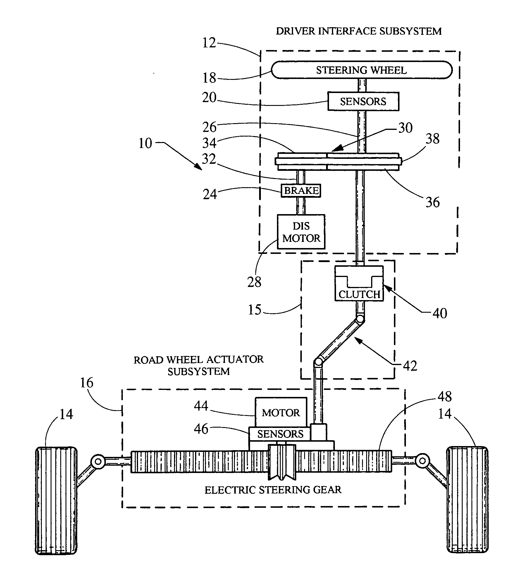
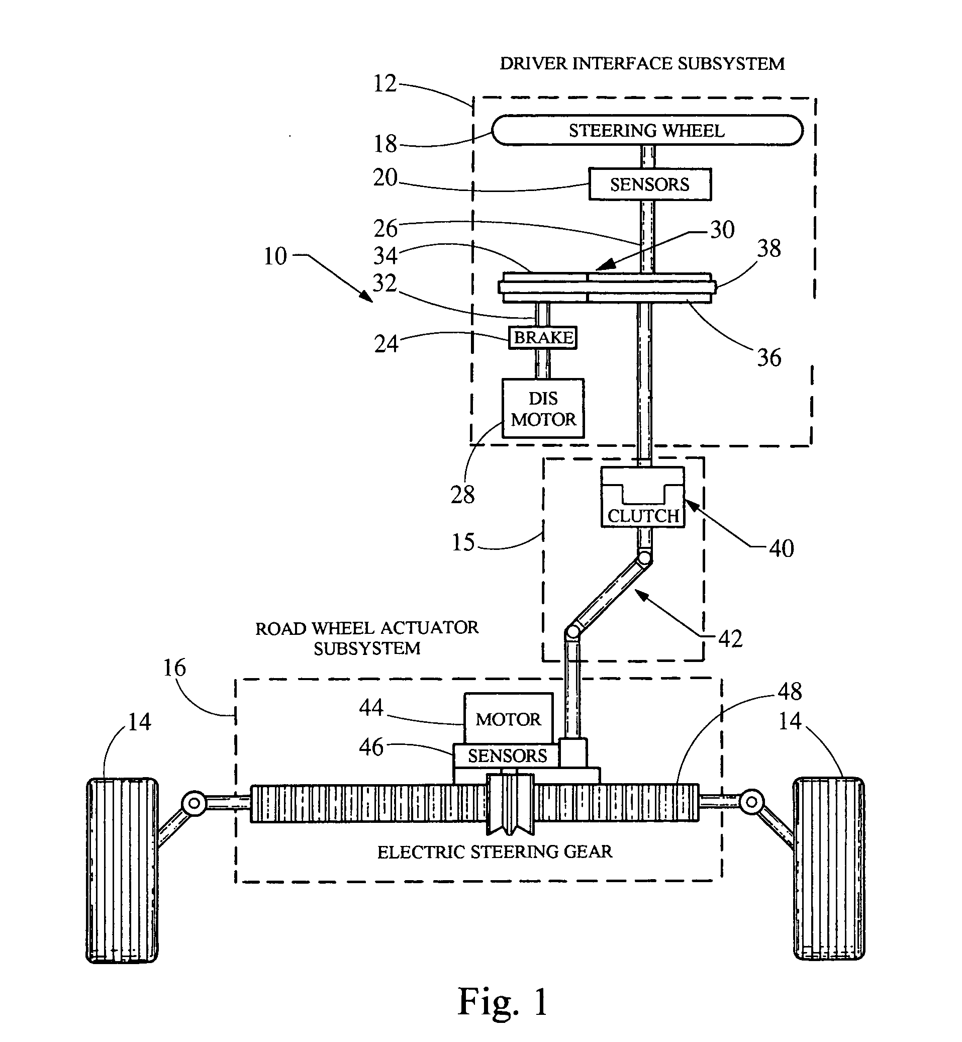
[0014] Referring now to the drawings, a steer by wire system embodying the principles of the present invention is illustrated therein and designated at 10. As its primary components, the steer by wire system 10 includes a driver interface subsystem 12, a manual backup steering subsystem 15, a road wheel actuator subsystem 16, and road wheels 14. The driver interface subsystem 12 is designed to sense the intent of the driver to control the road wheels 14. Further, the driver interface subsystem 12 also provides feedback to the driver corresponding to the instantaneous steering conditions.

[0015] Included in the driver interface subsystem 12 is a steering wheel 18, a series of sensors 20, a brake 24, a motor 28, and a steering shaft 26. The steering wheel 18 is connected to the steering shaft 26. As the steering wheel 18 is rotated, it causes the steering shaft 26 to be rotated in the same direction. The sensors 20 are connected to the steering wheel 18 or the steering shaft 26, and d...


PUM


Abstract

The present invention provides a system for generating an end of travel feedback to the driver of a vehicle where the vehicle includes a steer by wire system. The system includes a steering wheel, a steering shaft, a motor, and a brake. The steering wheel is configured to control the steer by wire system. The steering shaft is coupled to the steering wheel and rotates in conjunction with the steering wheel. To provide road feel resistance to the driver, the motor is coupled to the steering shaft. Further, the brake is coupled to a shaft of the motor and is adapted to provide mechanical resistance when the road wheel is at an end of travel position.

Description

BACKGROUND [0001] 1. Field of the Invention [0002] The present invention generally relates to a steer by wire system. More specifically, the invention relates to an end of travel and method for a steer by wire system. [0003] 2. Description of Related Art [0004] In a conventional steering system, the steering wheel is mechanically connected to the steering shaft. When the mechanical end of travel of the vehicle wheels or the steering gear is reached, (an “end of travel” condition), the steering wheel cannot be rotated any further due to high mechanical resistance. However, in normal operation a steer by wire system has no mechanical coupling to the steering gear. The lack of feedback torque for the driver at the end of travel condition is unfamiliar and uncomfortable for the driver. In addition, extensive use of the steering system in an end of travel condition such as the limit of steering gear travel or an against curb condition can cause additional wear to the vehicle and may lead...

Claims


Application Information

Patent Timeline
Patent Type & Authority Applications(United States)
IPC IPC(8): B62D5/00B62D5/04B62D6/00
CPCB62D5/005B62D6/008B62D5/0469B62D5/006
Inventor HUSAIN, MUQTADAOYNOIAN, JOHN G.SHIAH, KYI-SHINPALMER, ROBERT T.DAUGHERTY, BRIAN E.
Owner NISSAN MOTOR CO LTD
Why Eureka
Try Eureka