Plunger contact assembly for an automobile control stalk

Inactive Publication Date: 2005-04-21
METHODE ELETRONICS INC
View PDF15 Cites 2 Cited by
  • Summary
  • Abstract
  • Description
  • Claims
  • Application Information

AI Technical Summary

Benefits of technology

[0007] Therefore the present invention provides a contact assembly that moves in both the vertical and lateral direction, providing a self-cleaning mechanism by the movement of the contacts in the lateral direction. Furthermore, the present invention provides a contact assembly having fewer parts, thereby making it easier to assembly and lowering its cost. Also, the fewer number of parts reduces the number of parts that are susceptible to wear and fatigue, increasing the reliability of the contact assembly.

Problems solved by technology

Also, the fewer number of parts reduces the number of parts that are susceptible to wear and fatigue, increasing the reliability of the contact assembly.

Method used


Image

  • Plunger contact assembly for an automobile control stalk
  • Plunger contact assembly for an automobile control stalk
  • Plunger contact assembly for an automobile control stalk

Examples


Embodiment Construction

[0015] Referring now to the several drawing figures in which identical elements are numbered identically throughout, a description of the preferred embodiment of the present invention will be provided.

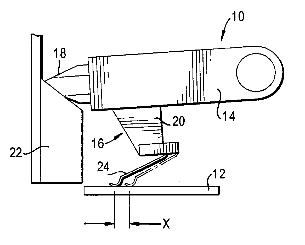
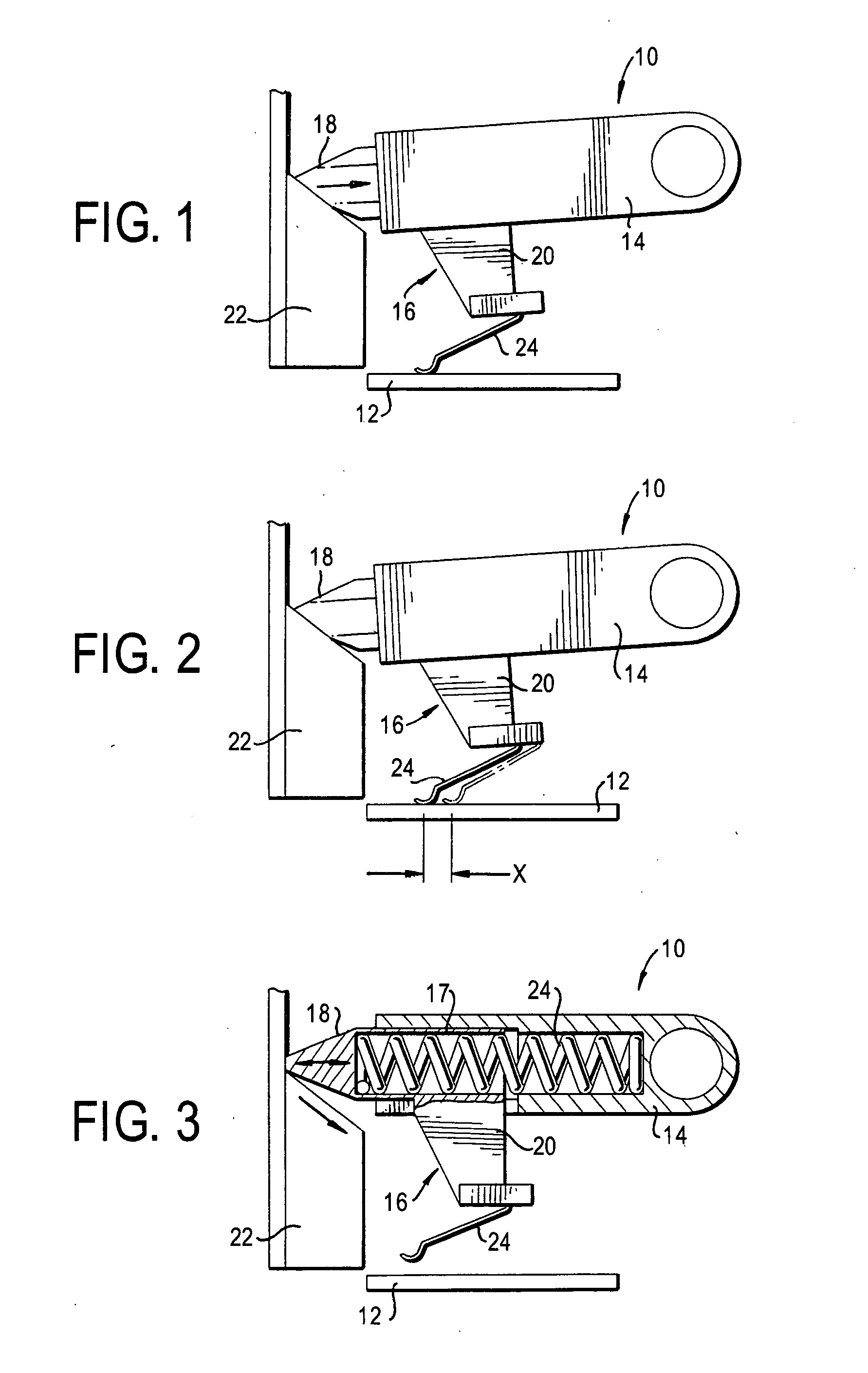
[0016]FIGS. 1-3 show side views of the contact assembly 10 of the present invention at various stages of operation. FIG. 1 shows the contact assembly 10 upon initial contact with a printed circuit board (PCB) or insert molded substrate 12, FIG. 2 shows the movement of the contact assembly 10 across the PCB 12, and FIG. 3 shows the contact assembly 10 prior to contact with the PCB 12.

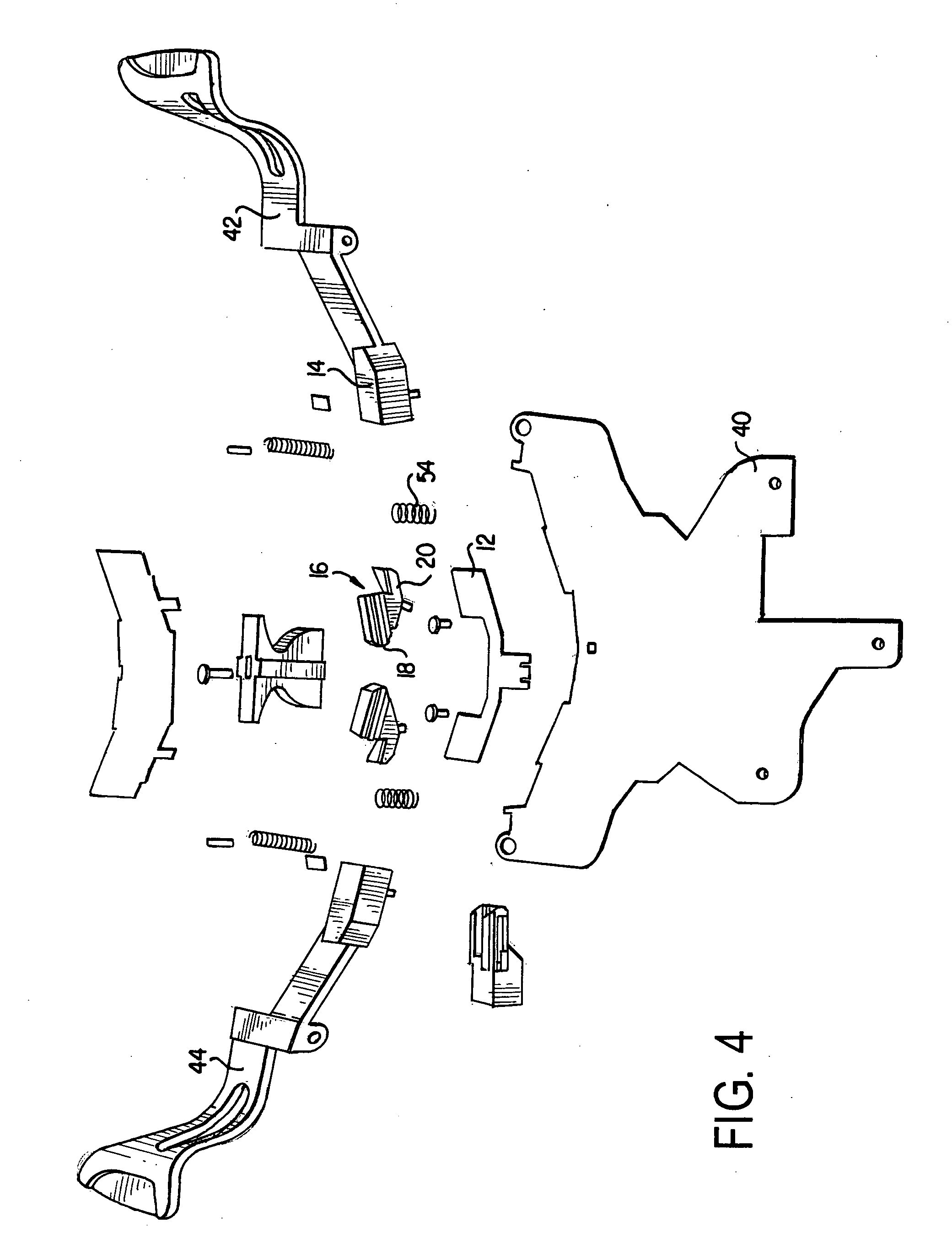
[0017] The contact assembly 10 comprises a housing 14 and a stalk 16 located therein. The stalk 16 is a reciprocating arm located within the housing 14 that includes a hollow shaft portion 17, an integrally formed forwardly extending tip portion 18 at one end of the shaft portion 17, and a downwardly extending contact arm 20 projecting from the shaft portion 17. This is best seen in FIG. 3, which shows th...


PUM


Abstract

The contact switch assembly comprises a rotating housing with a stalk having a hollow shaft portion, a tip portion extending forwardly from the shaft portion and a contact arm extending downwardly from the shaft portion. The tip portion extends out from the housing to engage an adjacent inclined surface. As the housing is rotated, the stalk moves along the inclined surface so that the contact arm is moved vertically and brought into engagement with a printed circuit board (PCB) while simultaneously moving laterally across the PCB's surface. The vertical motion is caused by the rotation of the housing, while the lateral motion is caused by the stalk being forced laterally by the inclined surface. The combination of both the vertical and lateral motion provides a self-cleaning mechanism by the movement of the contacts in the lateral direction.

Description

FIELD OF INVENTION [0001] The present invention is directed towards a electrical contact assembly for a control stalk of an automobile having a contact that moves both vertically and laterally (horizontally) to engage and sweep across the contact of a corresponding printed circuit board or insert molded substrate. BACKGROUND OF THE INVENTION [0002] Electrical switches and levers of various types are well known in the automobile art. Typically, these switches or levers have an actuation device that moves the contact element of a first device into engagement with the contact element of a second device. These types of switch assemblies can be the butting type where the electrical contact is pushed linearly into engagement with its corresponding contact, or the sliding or rotating dial type, where the electrical contact is moved along the plane of the corresponding contact from an “off” position to an “on” position. [0003] In the butting type lever, the contacts of the two devices repea...

Claims


Application Information

Patent Timeline
IPC IPC(8): B60Q1/14H01H1/18H01H1/40
CPCB60Q1/1469H01H21/18H01H1/403H01H1/18H01H3/00H01H9/04H01H9/00H01H3/02
Inventor CHARNOCK, MARTINBUTTERWORTH, J.A.
Owner METHODE ELETRONICS INC
Why Eureka
Try Eureka