
Inflatable cushion retention system

a cushion retention and inflatable technology, applied in the direction of pedestrian/occupant safety arrangement, vehicular safety arrangment, vehicle components, etc., can solve the problem of reducing the time required to place the cushion into the retaining system, and achieve the effect of convenient use, less cost, and simple design

Active Publication Date: 2005-04-21
AUTOLIV ASP INC
View PDF42 Cites 20 Cited by
  • Summary
  • Abstract
  • Description
  • Claims
  • Application Information

AI Technical Summary

Benefits of technology

The present invention is an airbag cushion retention system that addresses current problems in the art. The system is simple and less expensive than conventional systems, making it easier to install. It includes a supporting member with tabs attached to the cushion, which secure the cushion in a folded condition. The tabs interlock with apertures on the supporting member to retain the cushion. The system is designed to be easily installed and remove, reducing the time required for installation. Overall, the invention provides a more cost-effective and efficient solution for airbag cushion retention.

Problems solved by technology

In addition, the airbag retention system is easier to use than conventional systems, thus diminishing the time required to place the cushion into the retaining system.

Method used


Image

  • Inflatable cushion retention system
  • Inflatable cushion retention system
  • Inflatable cushion retention system

Examples


first embodiment

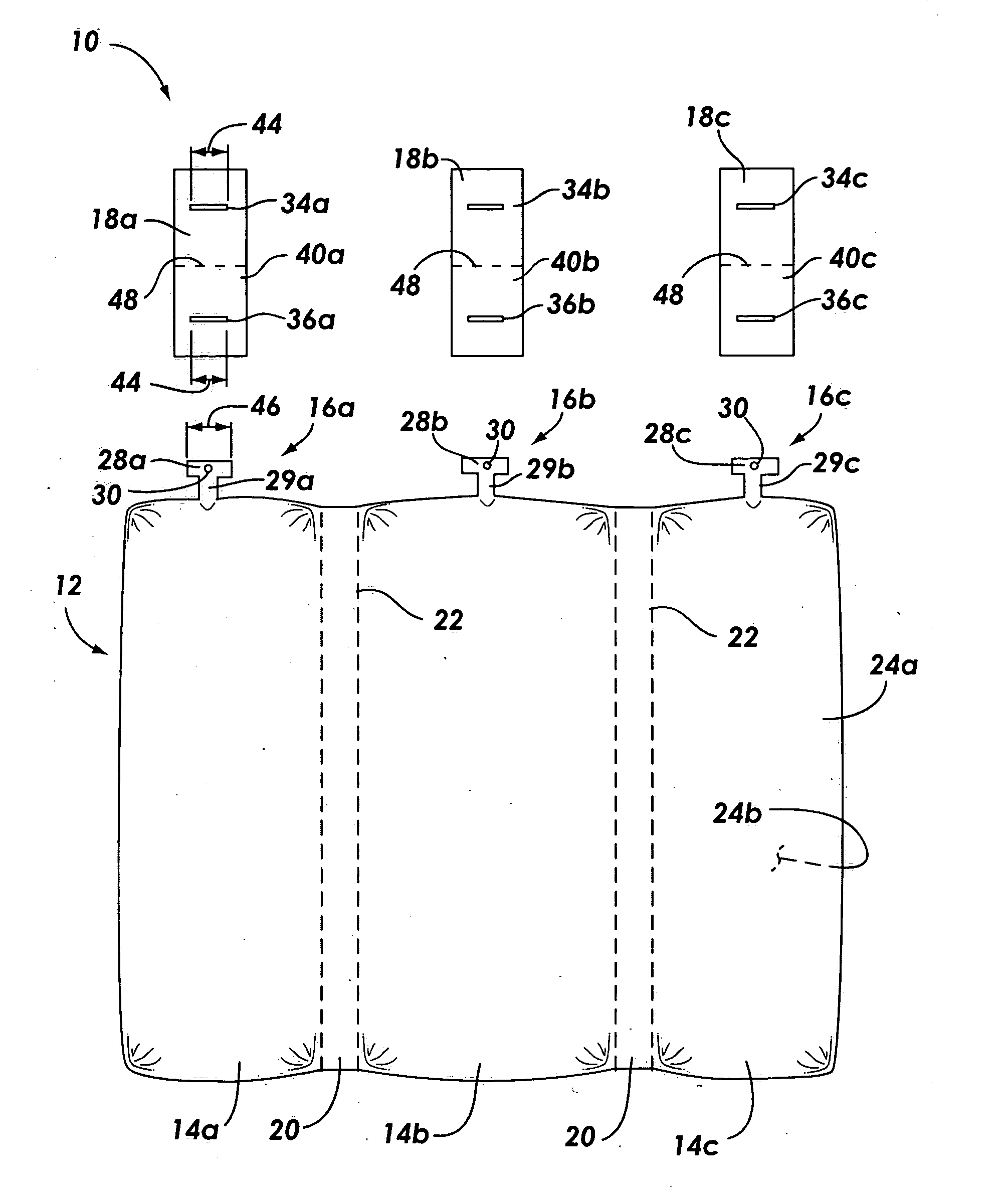
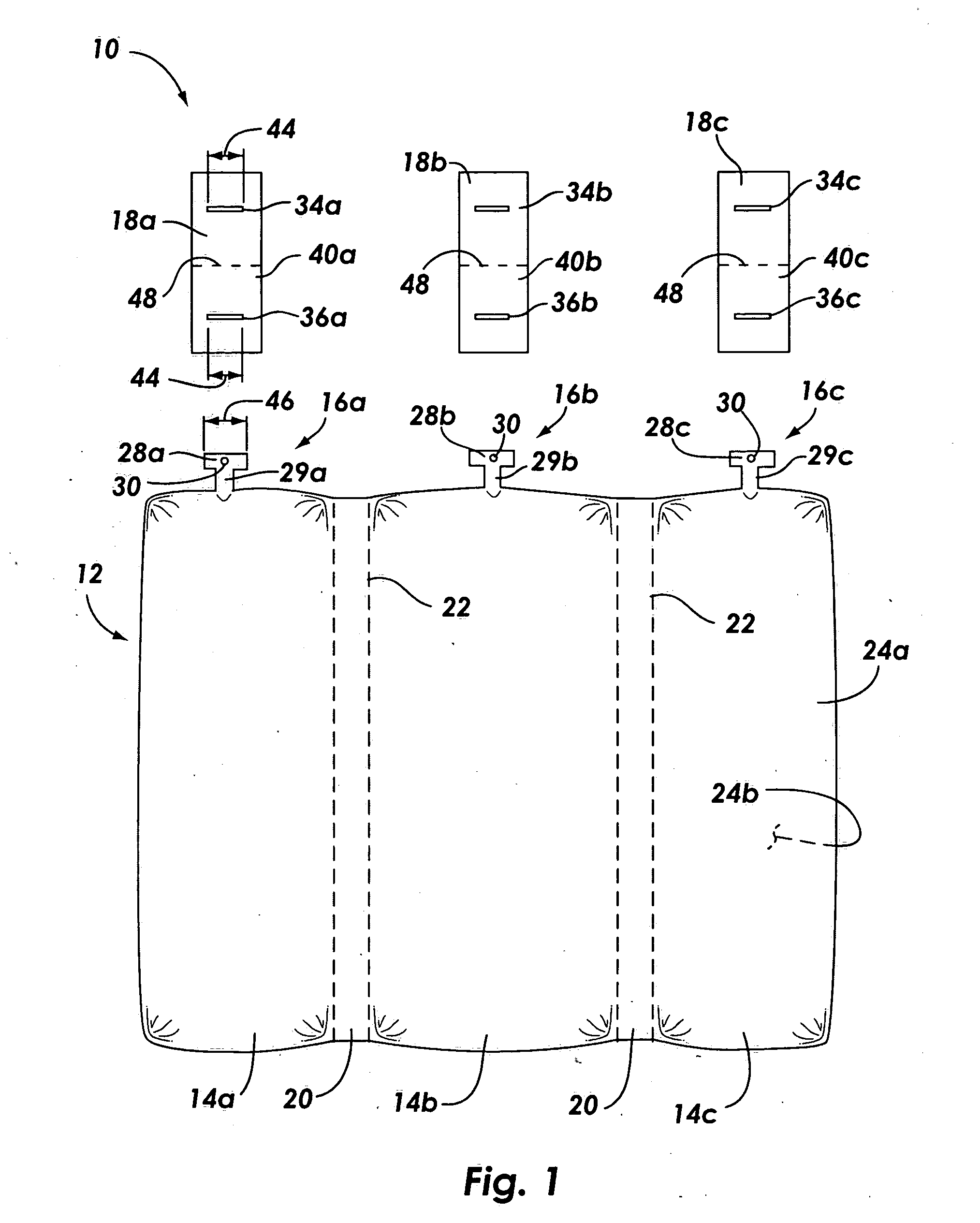
[0037] With reference to FIG. 1, there is shown a plan view of the cushion retention system 10 of the present invention. The system 10 includes an inflatable cushion 12 having one or more inflatable chambers 14a-c, tabs 16a-c attached to cushion 12, and supporting members 18a-c for retaining the cushion 12 in a folded condition.

[0038] The illustrated inflatable cushion 12 is an inflatable curtain 12 that is designed to deploy in a downward direction along a lateral portion of a vehicle (not shown). However, it should be noted that the system 10 of the present invention can be implemented with other types of cushions 12, such as driver's side cushions, passenger's side cushions, or knee bolster cushions.

[0039] Other variations of the illustrated cushion 12 also come within the scope of the present invention. For instance, the illustrated cushion 12 includes three chambers 14a-c having a divider 20 between each chamber 14. As illustrated in FIG. 1, the chambers 14 may be integrally f...

third embodiment

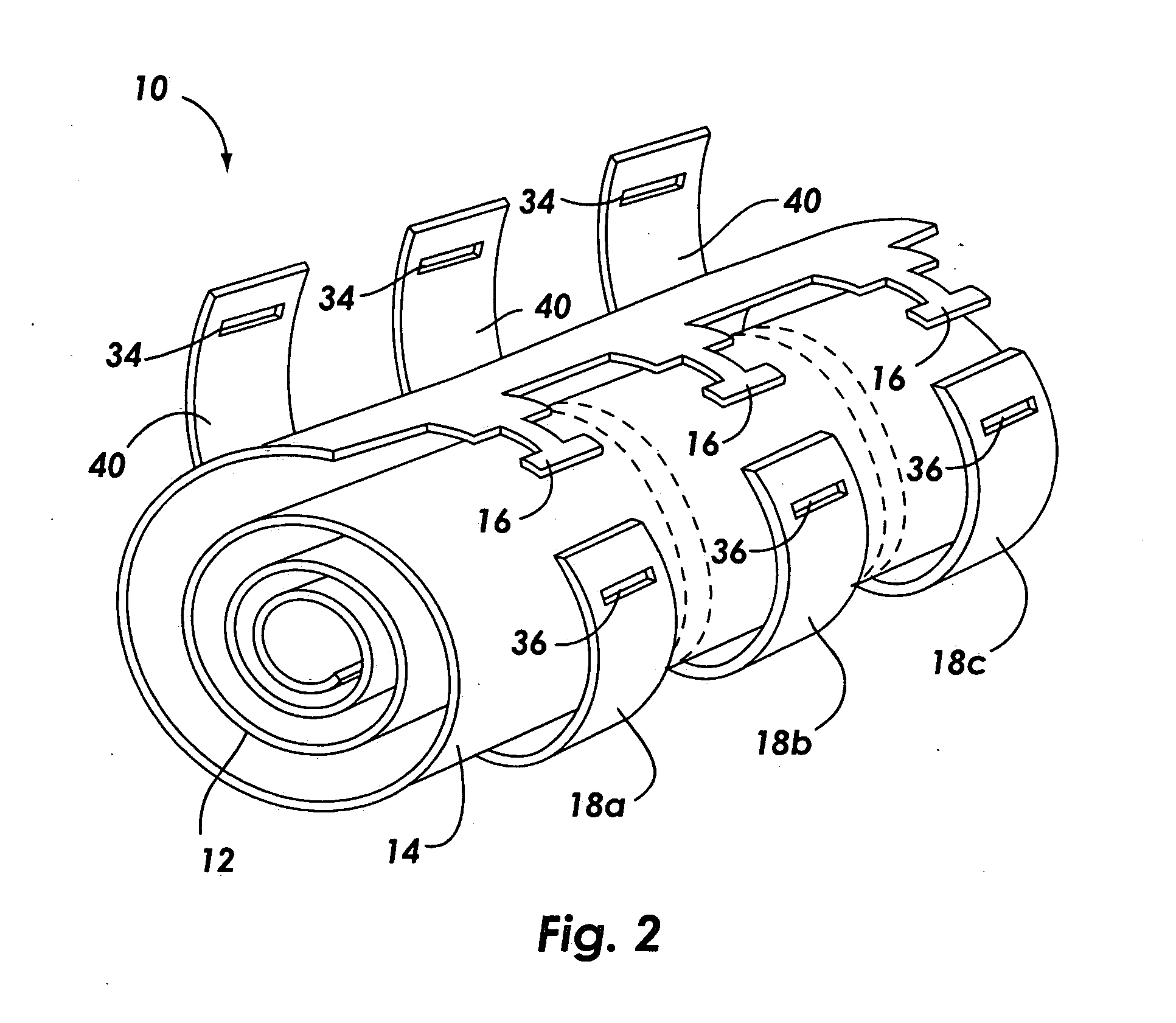
[0070]FIG. 6 depicts is a perspective view of cushion retention system 210 of the present invention with the cushion 212 shown in a folded condition. The illustrated cushion 212 shown in a rolled condition. However, those skilled in the art will recognize that alternative folding techniques may be used within the scope of this invention.

[0071] In FIG. 6, the intermediary region 240 of each supporting member 218 is disposed along an outer periphery 252 of the folded cushion 212. The tabs 216 have been inserted into and interlock with the apertures 234 of the extensible flap 225. In particular, the head 228 of each tab 216 has been inserted through an aperture 234 and retains the neck 229 of each aperture 234 within the corresponding aperture 234. In this condition, the supporting members 218 apply an inward compressive force to the chambers 214 to retain the chambers 214 in a folded condition.

[0072] The cushion retention system thus provides substantial advantages over conventional ...


PUM


Abstract

The cushion retention system includes a cushion, at least one tab attached to the cushion, and a supporting member having an intermediary region and at least one aperture. The cushion is positioned in a folded condition. The supporting member is disposed along an outer periphery of the cushion. The tab, which includes a head and a narrow neck, interlocks with the aperture on the supporting member to retain the supporting member along an outer periphery of the folded cushion. In this interlocked condition, the supporting members apply an inward compressive force to retain the cushion in a folded condition.

Description

BACKGROUND OF THE INVENTION [0001] 1. Field of the Invention [0002] The present invention relates to inflatable airbag systems. More specifically, this invention relates to a system for retaining an inflatable cushion in a folded condition. [0003] 2. Description of Related Art [0004] Inflatable airbags are well accepted for use in motor vehicles and have been credited with preventing numerous deaths and injuries. Some statistics estimate that frontal airbags reduce the fatalities in head-on collisions by 25% among drivers using seat belts and by more than 30% among unbelted drivers. Statistics further suggest that with a combination of a seat belt and an airbag, serious chest injuries in frontal collisions can be reduced by 65% and serious head injuries by up to 75%. Airbag use presents clear benefits and vehicle owners are frequently willing to pay the added expense for airbags. In addition, the inclusion of inflatable safety restraint devices, or airbags, is now a legal requiremen...

Claims


Application Information

Patent Timeline
Patent Type & Authority Applications(United States)
IPC IPC(8): B60R21/16B60R21/20B60R21/231
CPCB60R21/201B60R21/2342B60R21/231
Inventor TALLERICO, ROGERWELFORD, RICHARDGAMMILL, KURT
Owner AUTOLIV ASP INC
Learn More